Never look at the sun without eye protection!
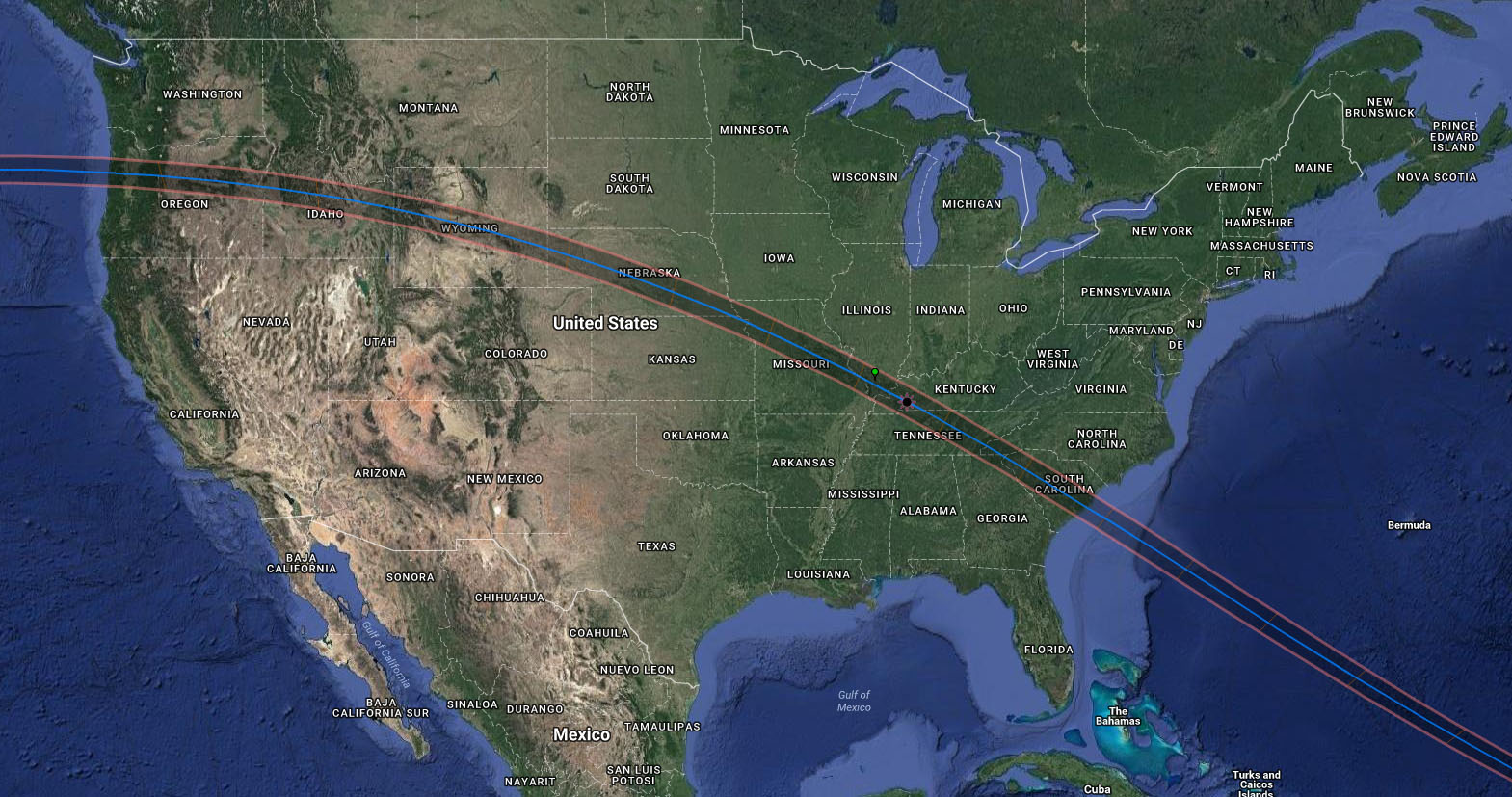
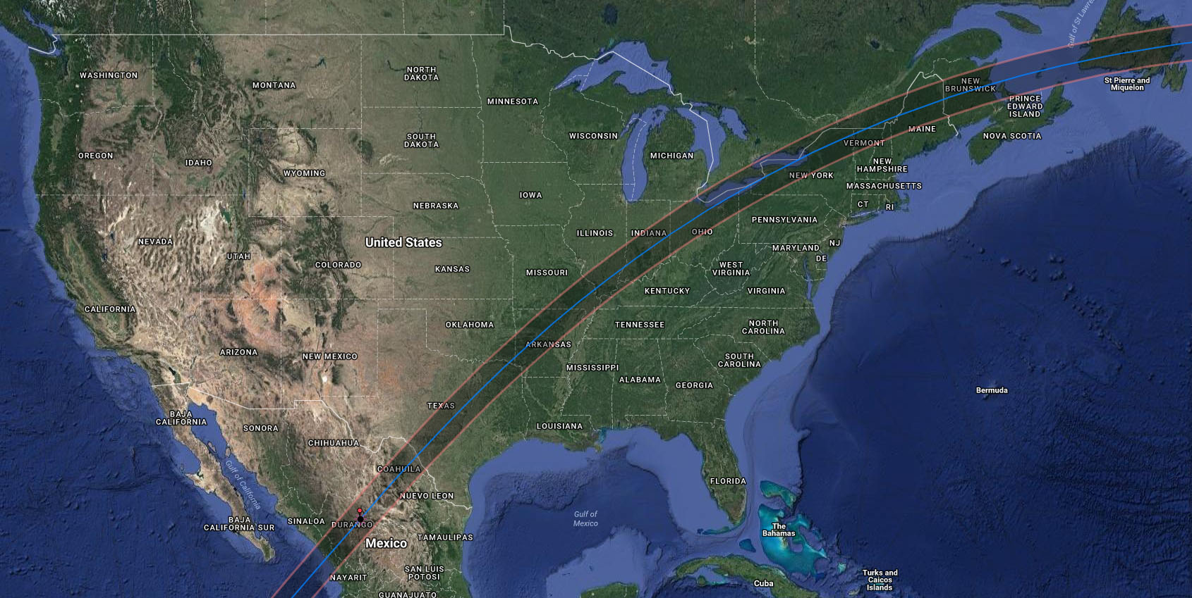
If you didn’t already know, in August of this year there will be a total solar eclipse across a swath through the center of the United States from Oregon to South Carolina. Given the rarity of such an event many people, including yours truly, are planning to make the trip to see the eclipse somewhere along the path. While others will see a partial eclipse from regions outside the band, only those along the marked path will see the Sun totally blocked by our Moon.
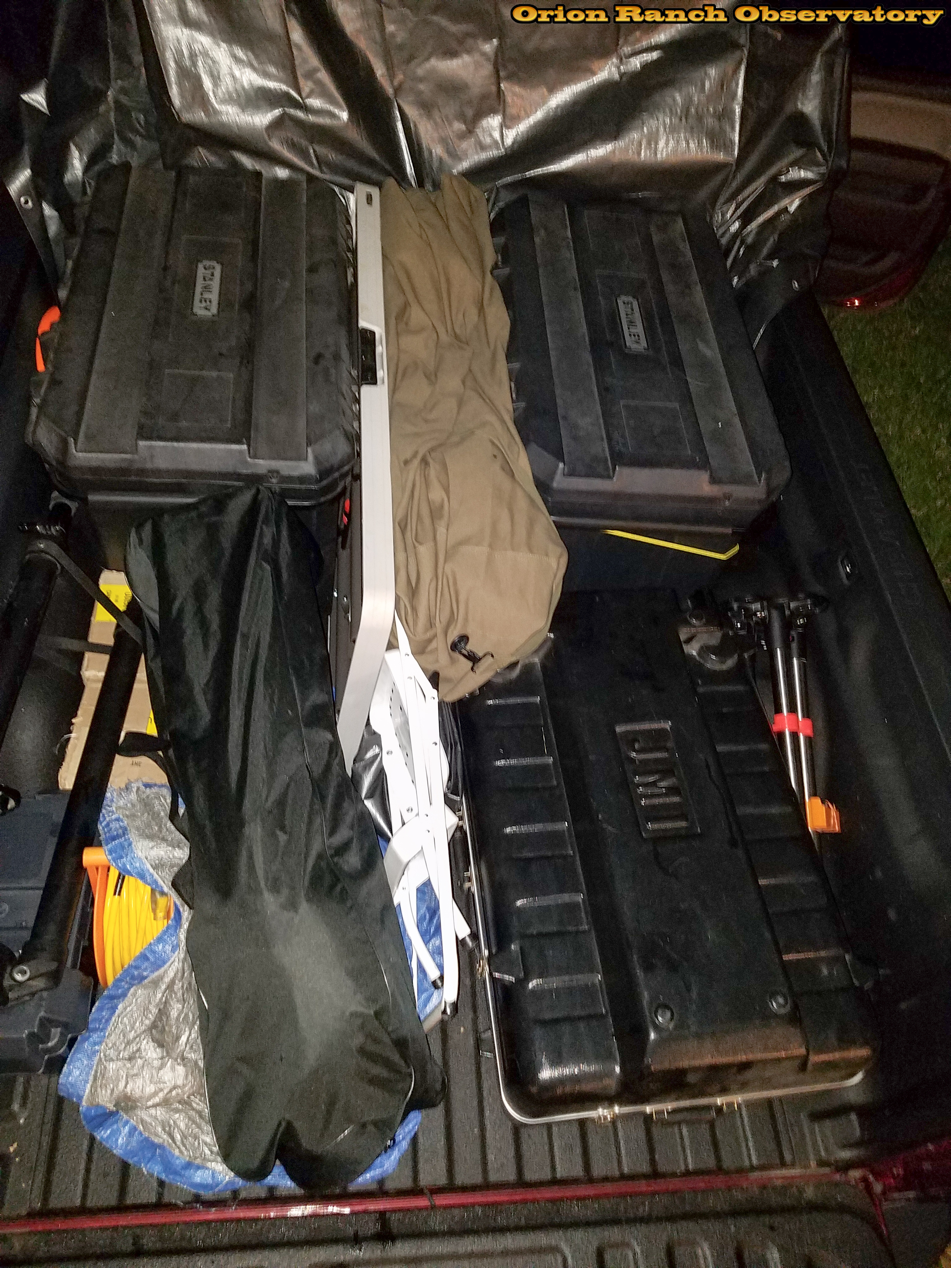
To that end, I’ve been working on plans to go to a location within the totality region and try to set up for a day of observing and photography throughout the eclipse. I can’t justify the trip to the West Coast where weather is likely to be the best, so I’ve restricted myself to an arc with a maximum of about a thirteen hour drive from Austin, TX. However, since the weather and cloud cover are a complete unknown, from this distance it doesn’t make sense to restrict myself to a single location. On the other hand, hotels and camp sights are rapidly filling or already sold out along the center-line of the eclipse, with some of the regions catching on and offering their few rooms for $400 or more a night. In order to hedge my bets against the weather and other factors, I’ve made reservations at hotels along that arc from Kearny, NE to just past Lebanon, TN, and will make the final decision on where to go a few days before the eclipse.
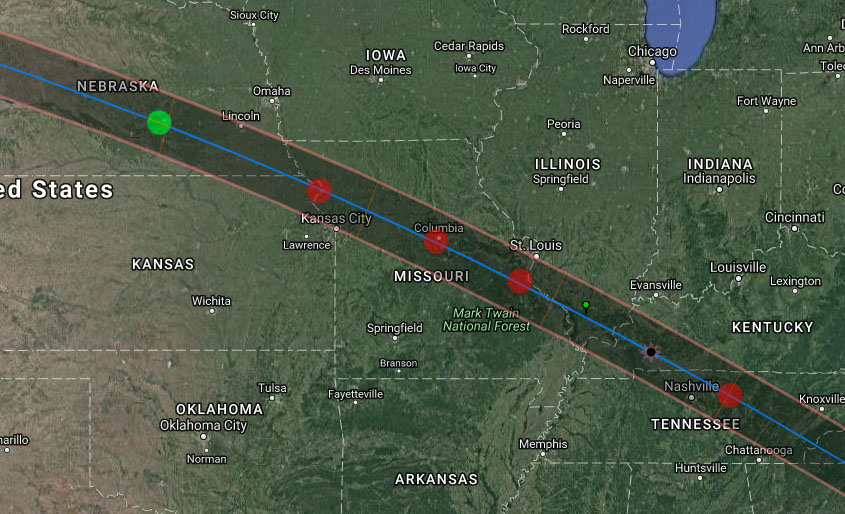
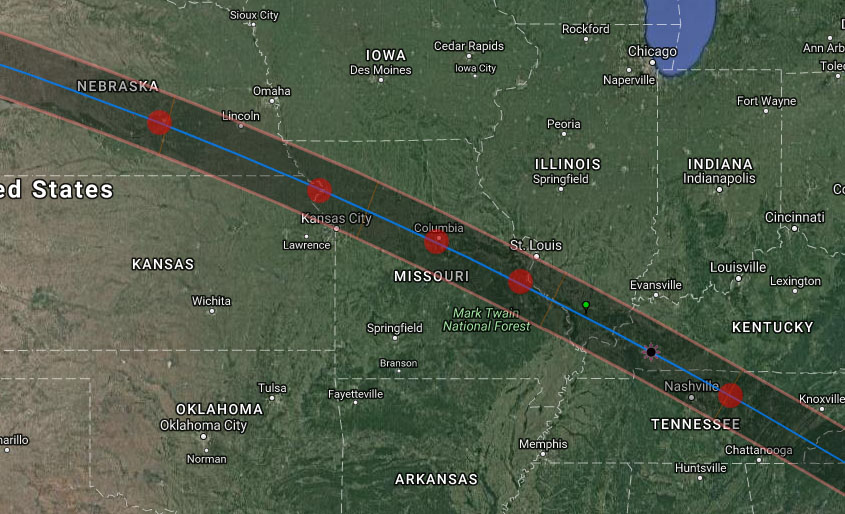 Potential observing locations highlighted by red dots.
It’s easy to find information on the eclipse with a simple web search, but eclipse2017.org has put together a very good set of resources and links, including viewing locations and an article on why you must see the total eclipse and not just a partial eclipse. There’s also plenty of good information on viewing and safety, as well as links to buy viewing glasses. Always remember,
Never look at the sun without eye protection!
And if it doesn’t work out for me this time, or if you don’t get a chance to go somewhere to see it, those of us in Central Texas will get another chance in 2024, when we will get a beautiful view of a total solar eclipse across most of the Hill Country, crossing through Fredericksburg, Marble Falls, and on up through Dallas, and catching Austin at the edge of the much wider band of totality. The Austin Astronomical Society dark sky site at Canyon of the Eagles on the north side of Lake Buchanan is directly under the center-line, while Orion Ranch Observatory will have almost as good of a view with well over four minutes of totality (compared to about 2.5 minutes max for the 2017 eclipse).
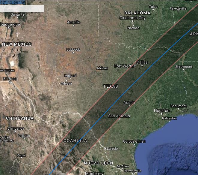 Path of 2024 solar eclipse through Texas.
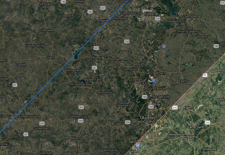 Region of 2024 solar eclipse totality covering Central Texas cities including about half of Austin.
So happy observing! I hope you get a chance to see something like this as it’s something you’ll never forget. And always remember:
Never look at the sun without eye protection!

 I’ve debated having an option for direct-printing of the various photos on the website here, and while most all of the images can be downloaded full size and printed by individuals, I’ve found an approach that I think will be best. I’ve sourced a print-on-demand shop that can create posters, mugs, T-shirts, and the like and that will integrate directly into my website shop. Rather than just printing anything, I will be developing customized artwork for specific products using the best of what I have available. I’ve put a couple of items online starting with a new eclipse poster and a couple of mugs. I’ll be adding more items as I have time to develop artwork I’m pleased with, but requests are welcome.
 I’m setting this up to pass through the price and shipping costs from the printer, with only a nominal markup for my artwork, depending on the item. I still have some work to do with the integration to deal with tax issues and the like, since California and North Carolina residents must pay tax because the printer operates in those states. I also recommend that if you want to order any of my other offerings along with your POD products that you split them into two orders. That will ensure the fastest delivery since dedicated POD orders are processed automatically, while mixed orders require intervention.