I finally sold the used 8SE that I’d picked up, so I pulled out my original 8SE to use at the TXMOST star parties we’ve been having every Friday. Unfortunately when I got there and set everything up, I discovered that I probably should have kept the one I sold! The mount had a tremendous amount of vibration from the slightest touch; something I recall now from when I used it before. If I pushed on it at all, the azimuth axis would move back and forth noticeably (several degrees of play). What I didn’t realize until just then was that this mount had always been defective and never performed as it should. The used mount I had performed much better than the one I’d bought new. So after years of working on other Celestron mounts that more often than not do not arrive from the factory in peak operating condition, I wasn’t afraid to tear into this mount and take care of it.
As I reassembled the mount, I took a picture log to give others an indication of how to disassemble/reassemble this mount. I’ll post a few images here, but see the gallery for more detail.
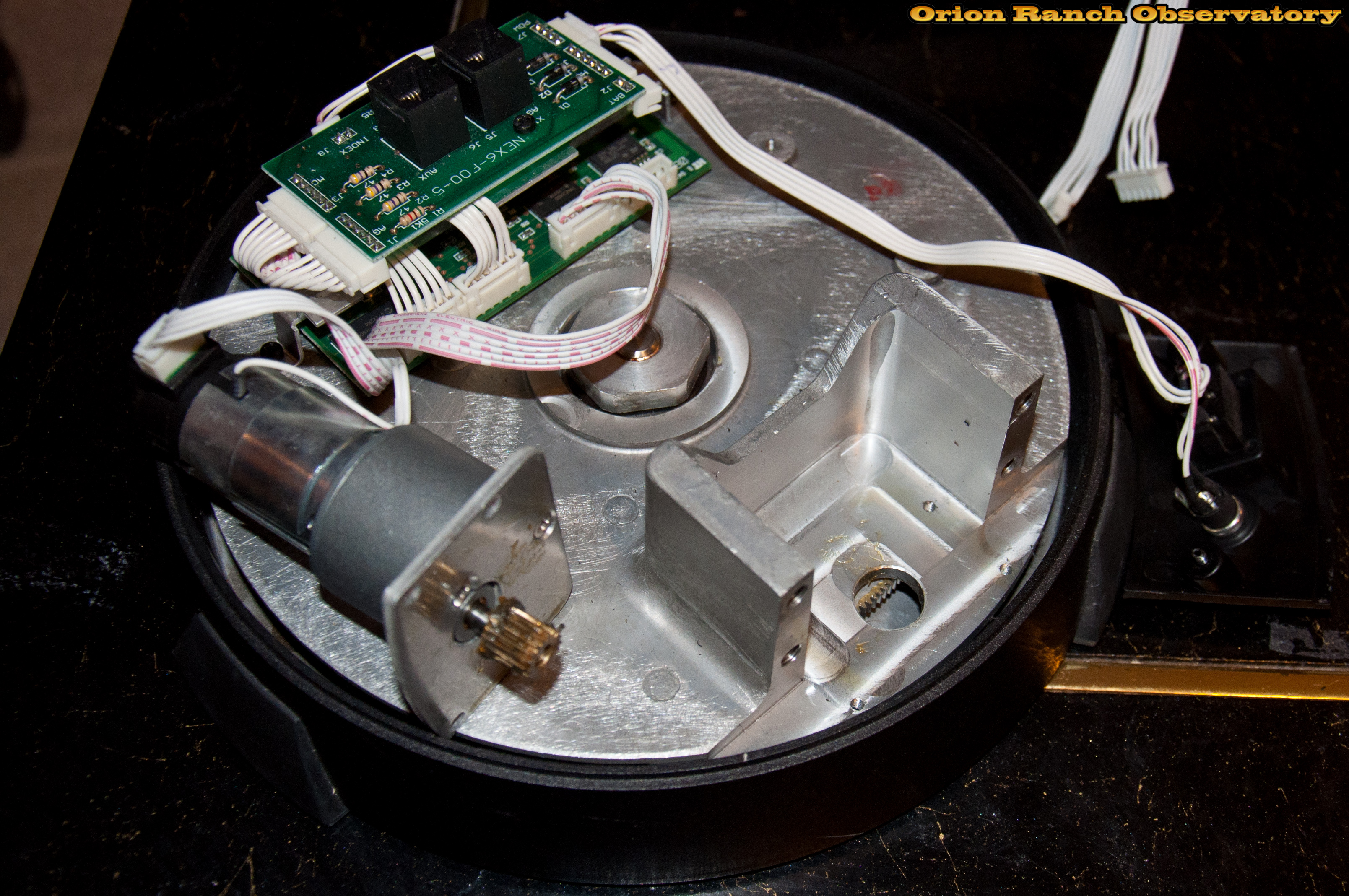
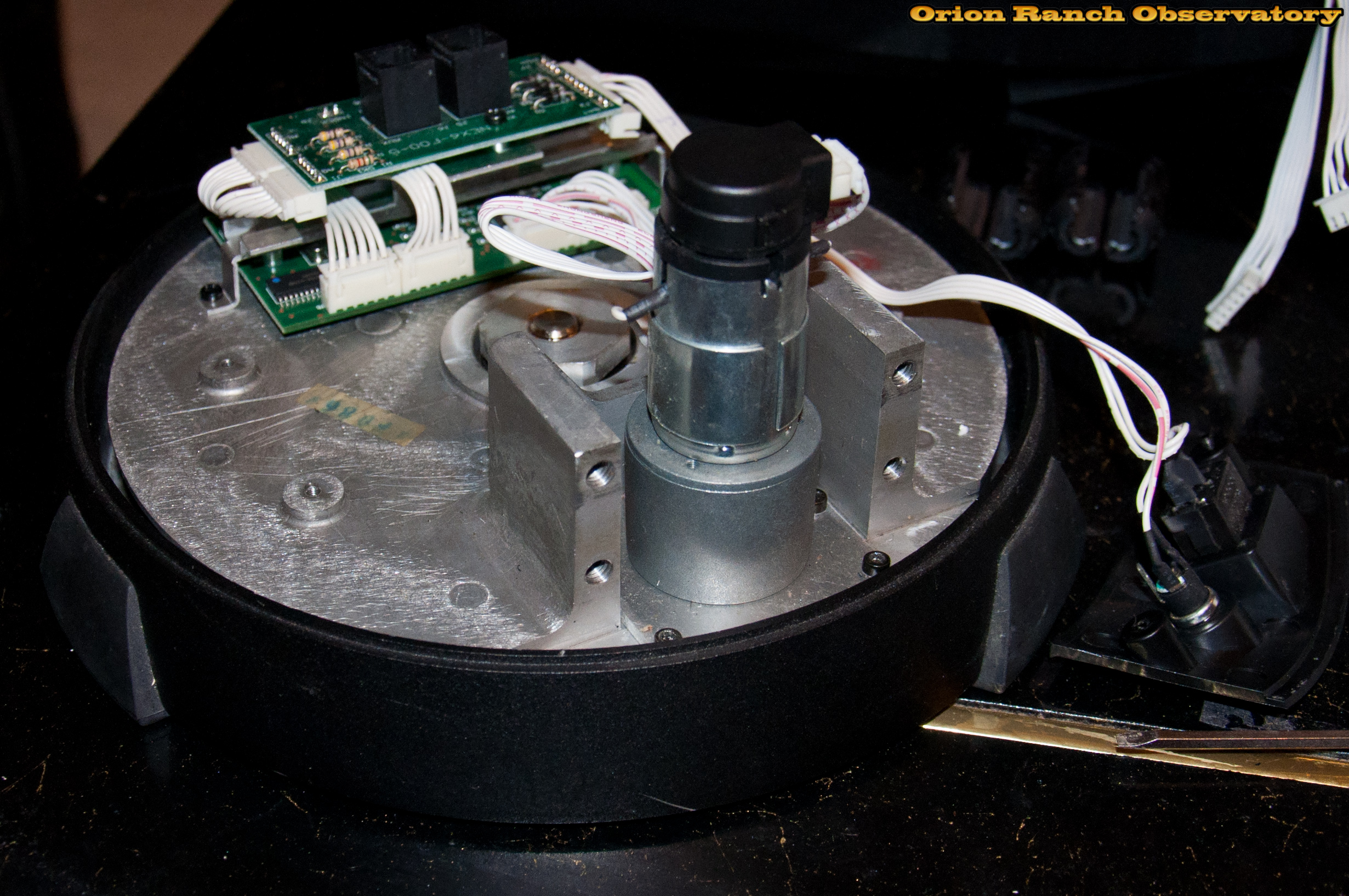
Here’s the NexStar mount disassembled down to the base to gain access to the motor and drive spur gear for the azimuth axis. Note too the motor control board with the interface board on top. The design is very simple.
 |
 |
Here’s a close-up of the stack up of interface and motor control boards. These are the only PCBs in the entire mount.
 |
|
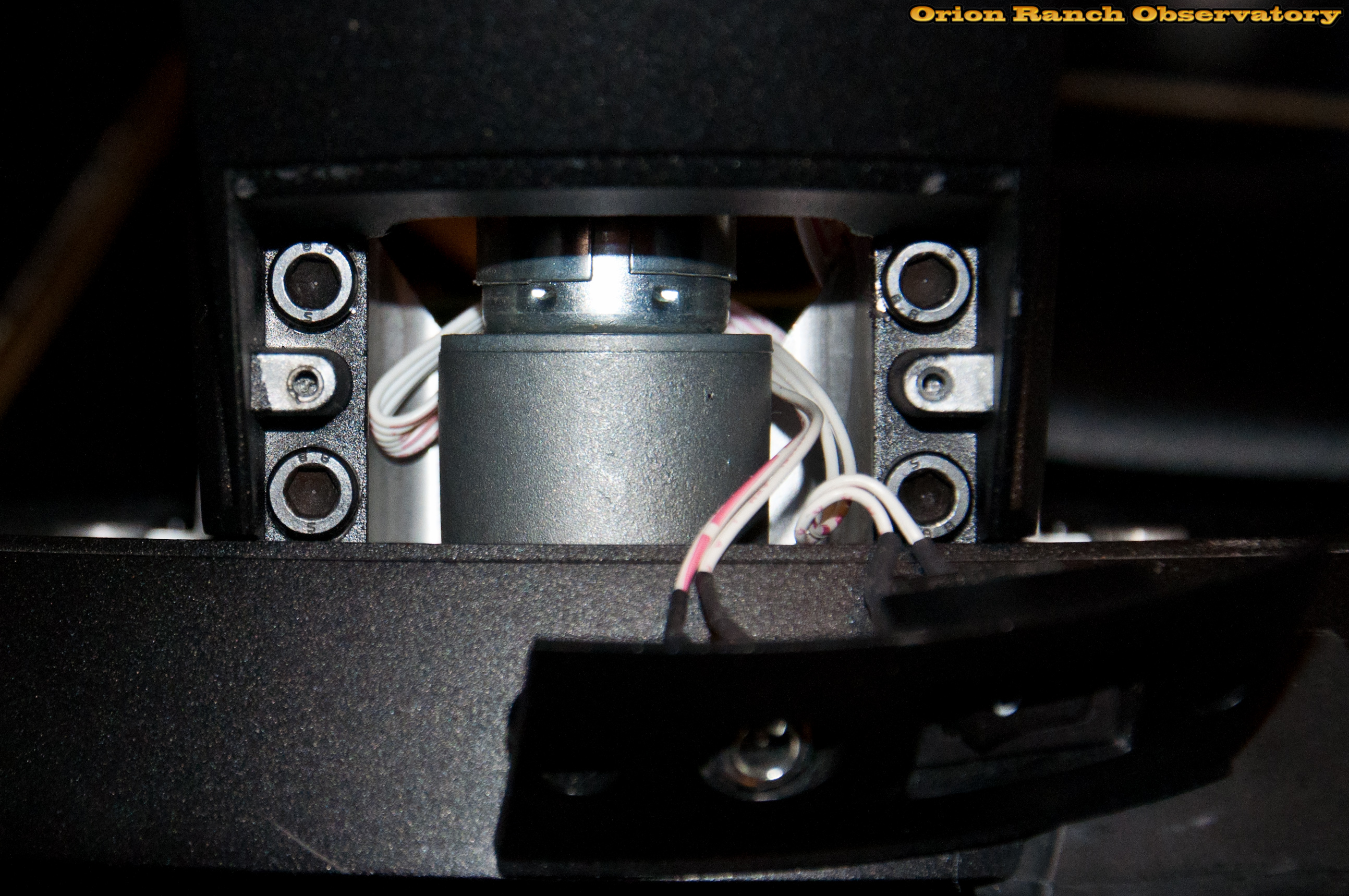
There are two ferrite cores clamped on each of the motor and interface cables. One in the base and one in the arm.
 |
|
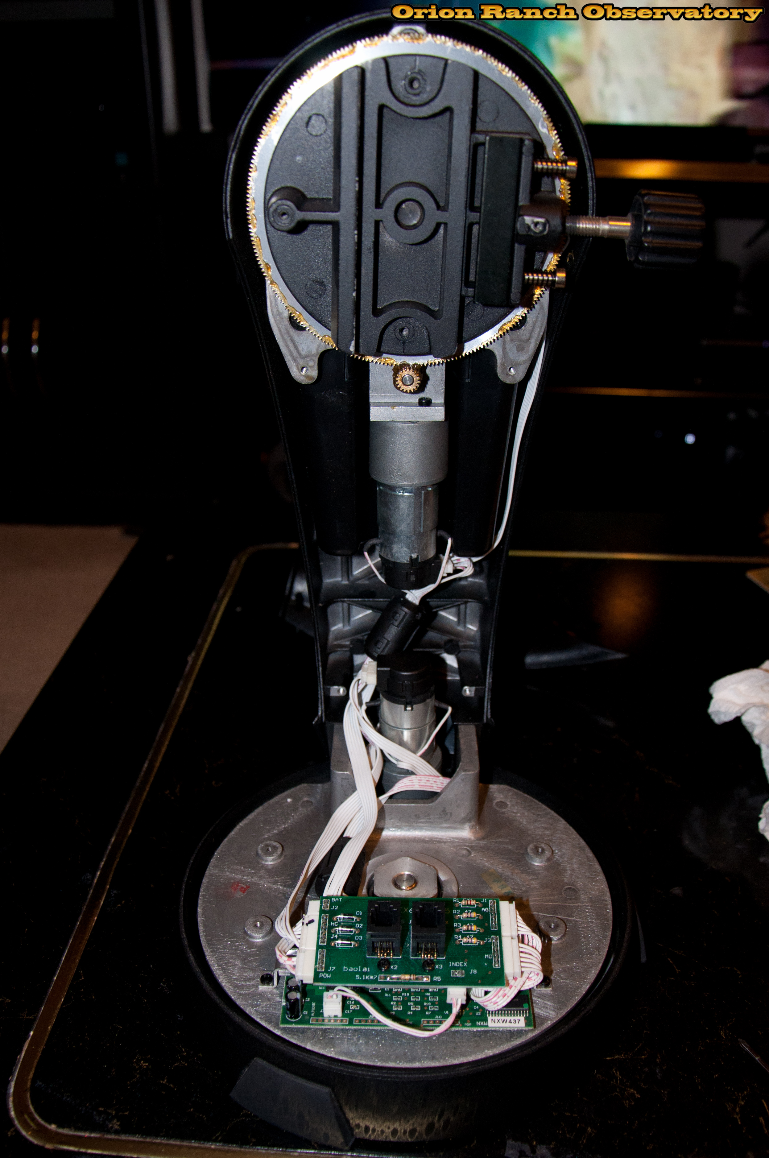
Here’s a view of the arm and elevation drive system. I didn’t make any modifications or adjustments to it this time. The plastic cover is held with four screws.
 |
|
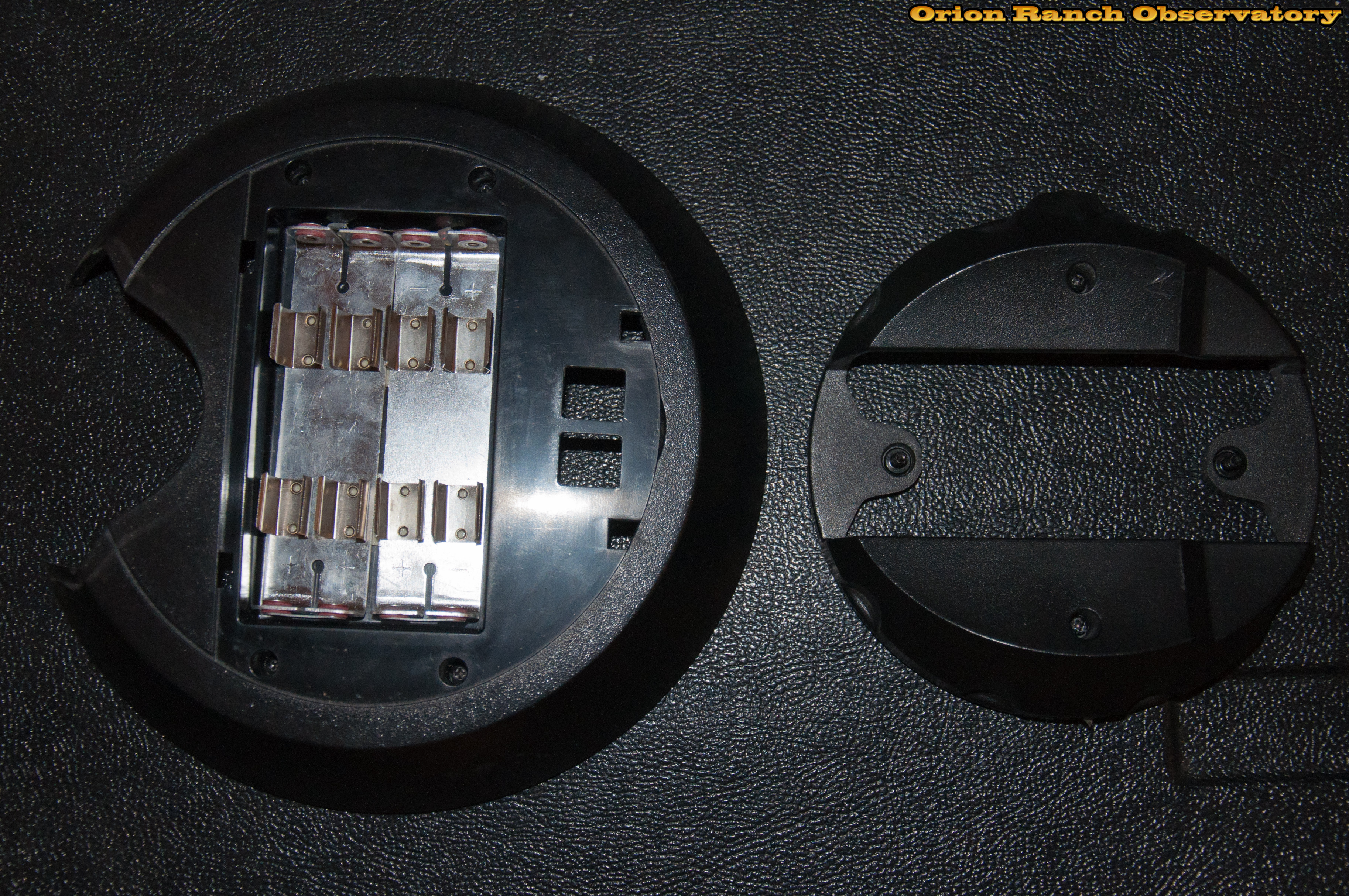
Views of the base cover with battery compartment (just unplugs from the interface board) and the cover around the OTA clamp.
 |
|
After re-installing the azimuth motor and pushing it tight to the spur gear to eliminate play in the azimuth axis, the drive is much tighter now. There’s quite a bit of adjustment in the four screw holes.
 |
|
Four socket head cap screws hold the arm to the base above the azimuth drive motor and behind the power switch plate.
 |
|
Here’s a view of the assembled mount components and cables before re-installing the covers. Note the location of the ferrites. Oops, that bottom ferrite should probably be clamping all four cables (don’t recall now if it did or not). Doubt I’ll get in to change that though.
 |
|
See the remaining images in the gallery.