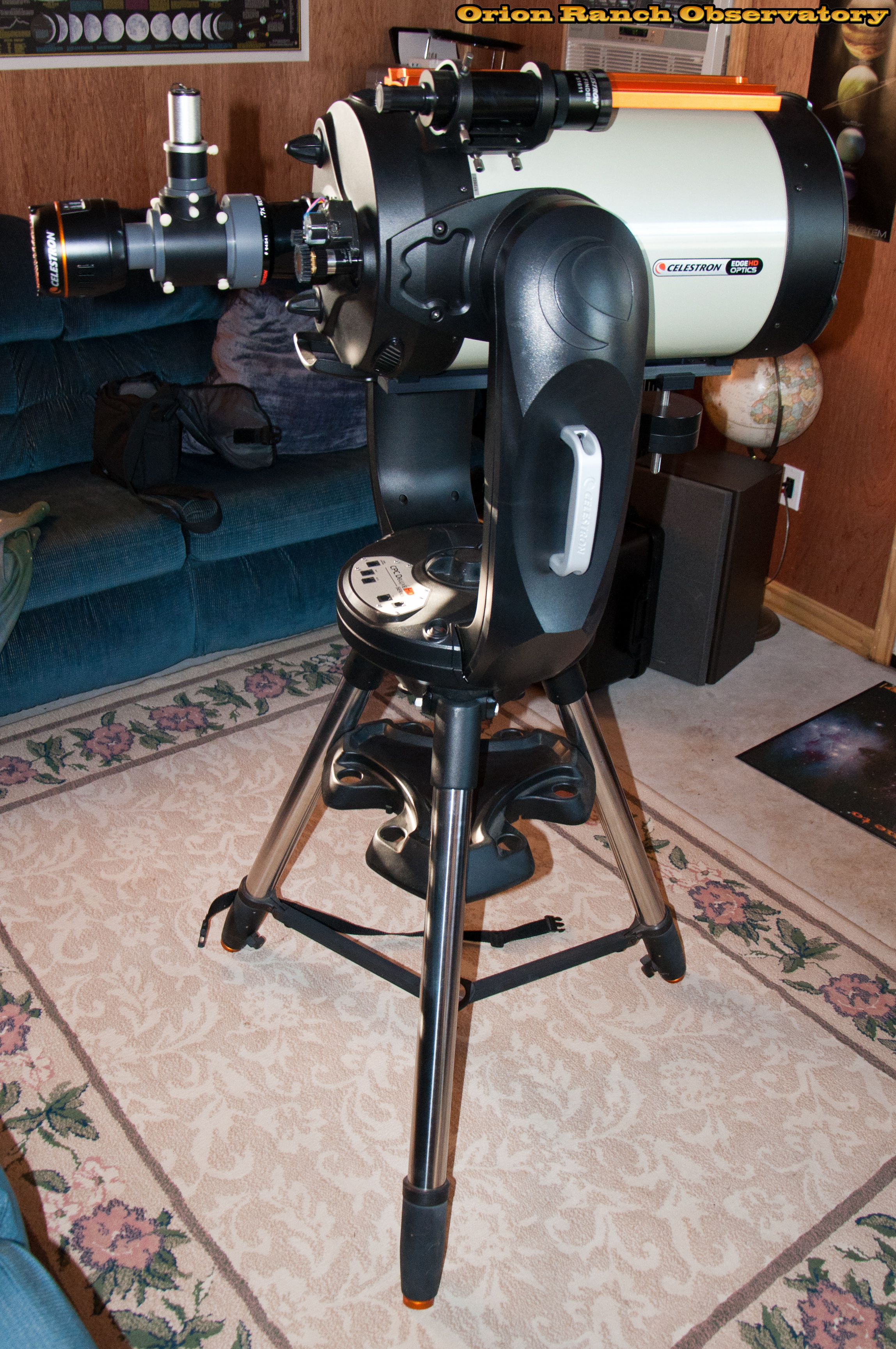
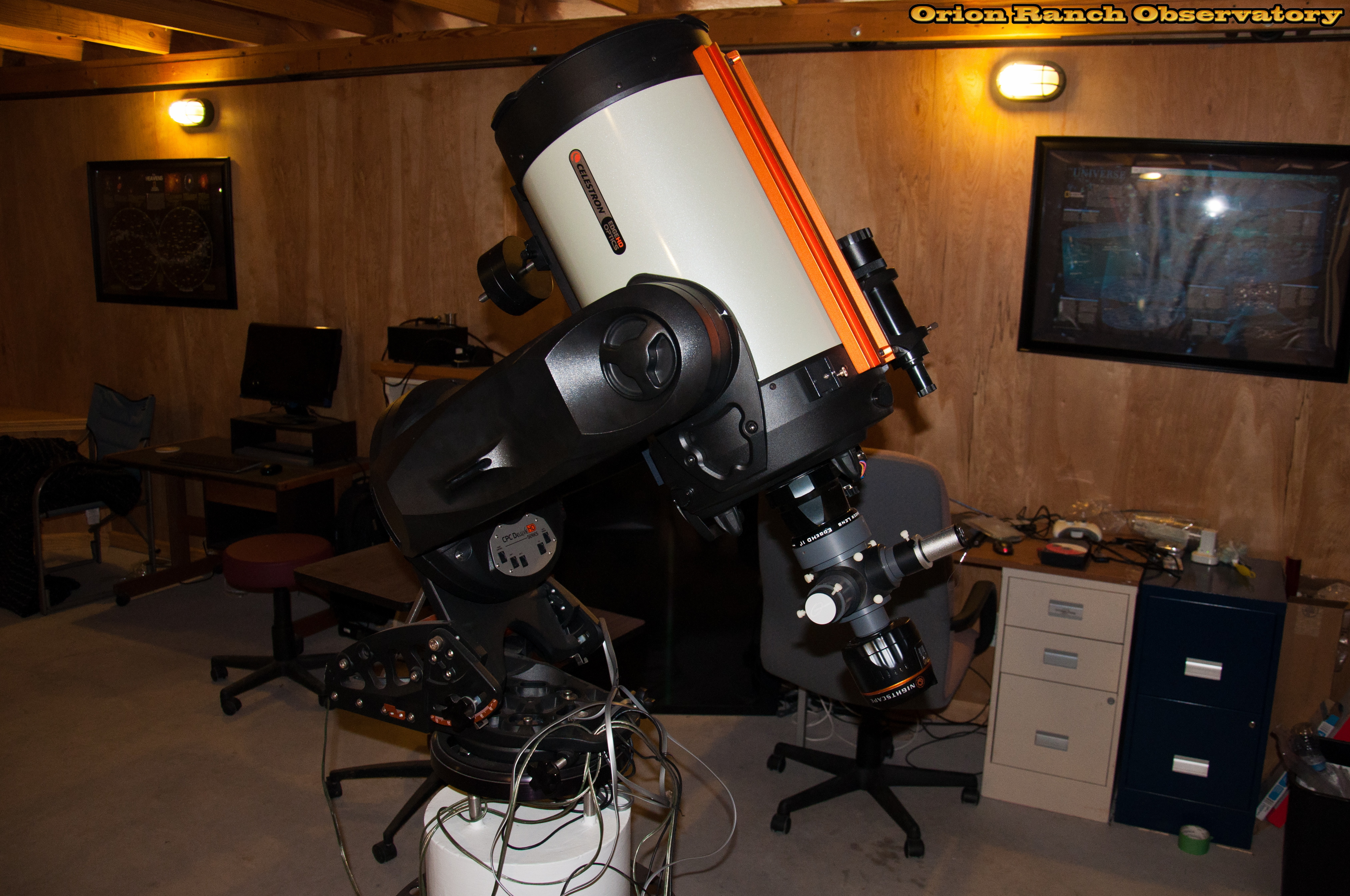
After completing the bearing upgrade on the azimuth/RA axis of my Celestron CPC Deluxe 1100 HD 11″ EdgeHD telescope, I followed up with a rebuild of the elevation/declination axis drive. This effort was more about addressing issues with the drive mechanism itself rather than just working on the bearings.
The EdgeHD was still on the tripod in the warm room from the azimuth axis rebuild.
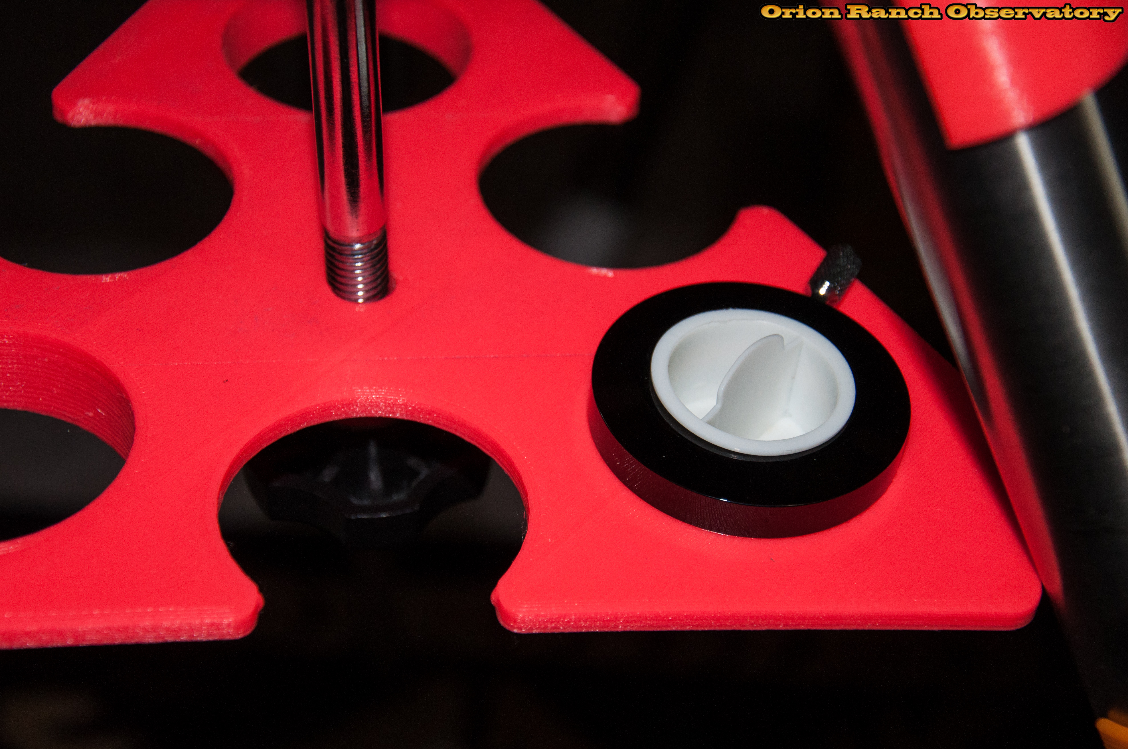
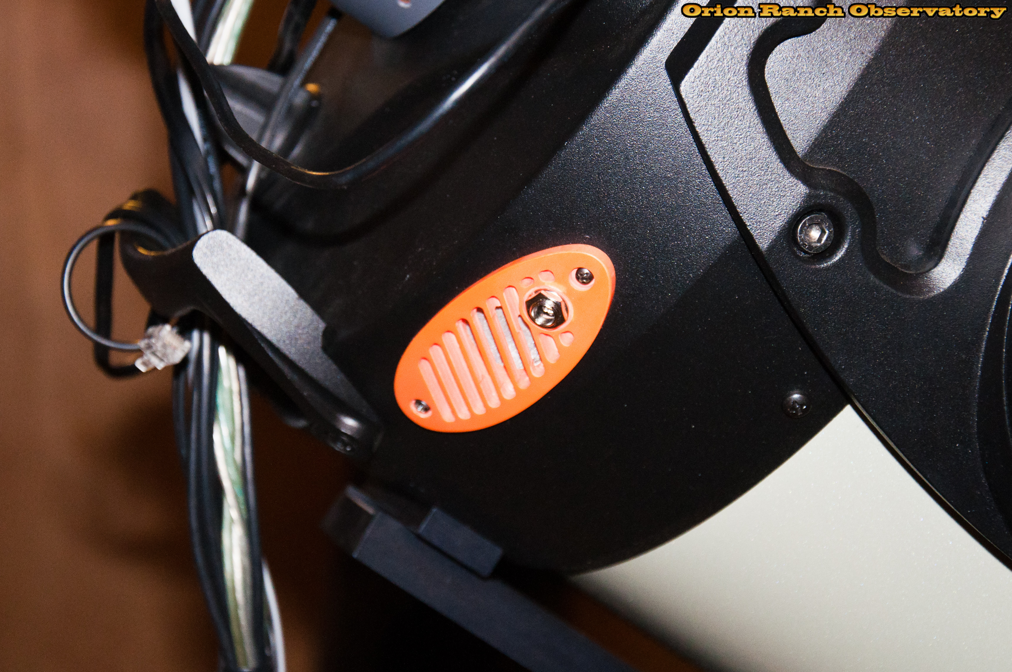
I started by removing the clutch knob by loosening the setscrew that captures it and unscrewing, just like the azimuth axis. In fact, several of the clutch parts are identical to the azimuth axis, and the procedure is the same.
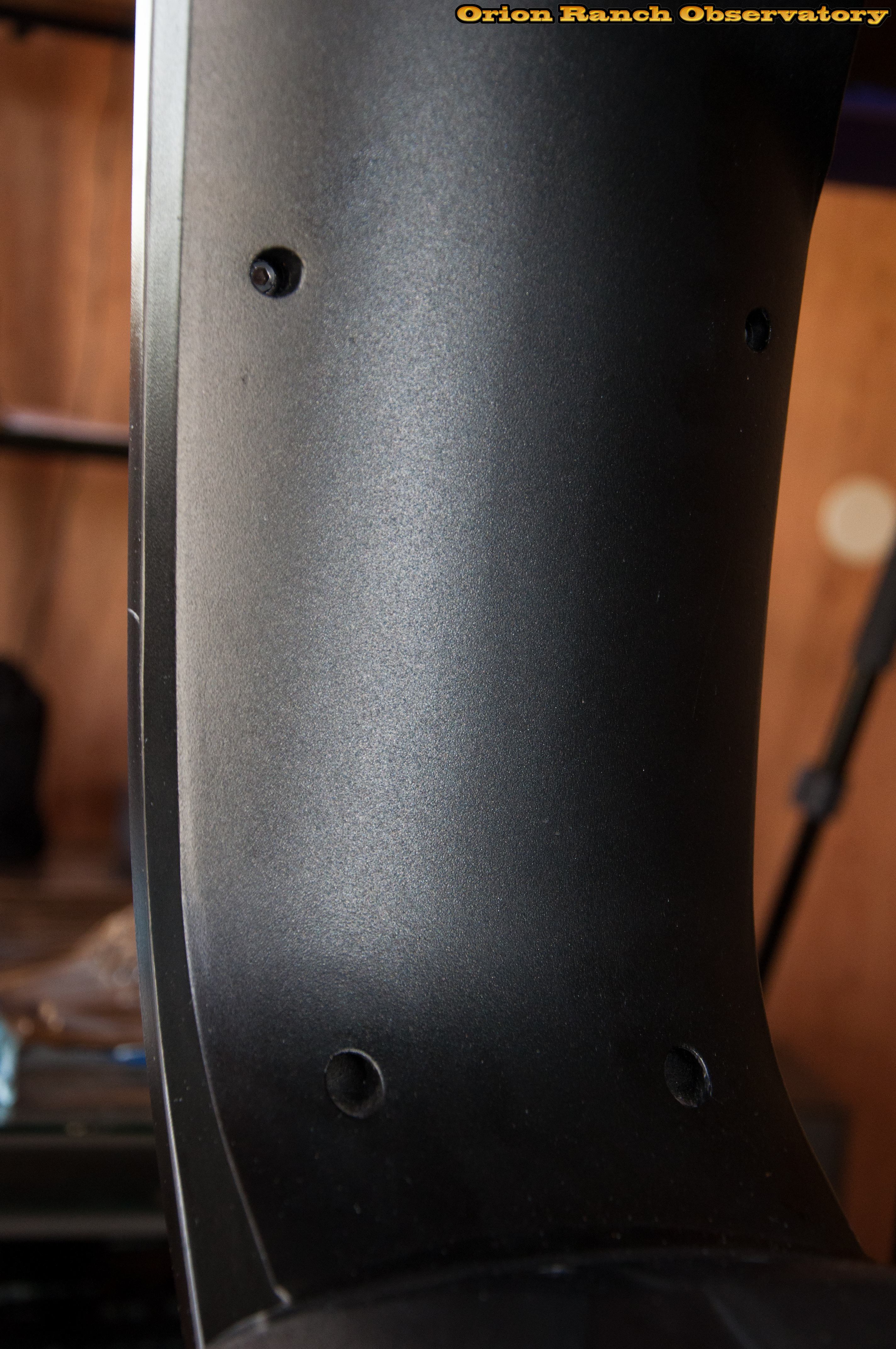
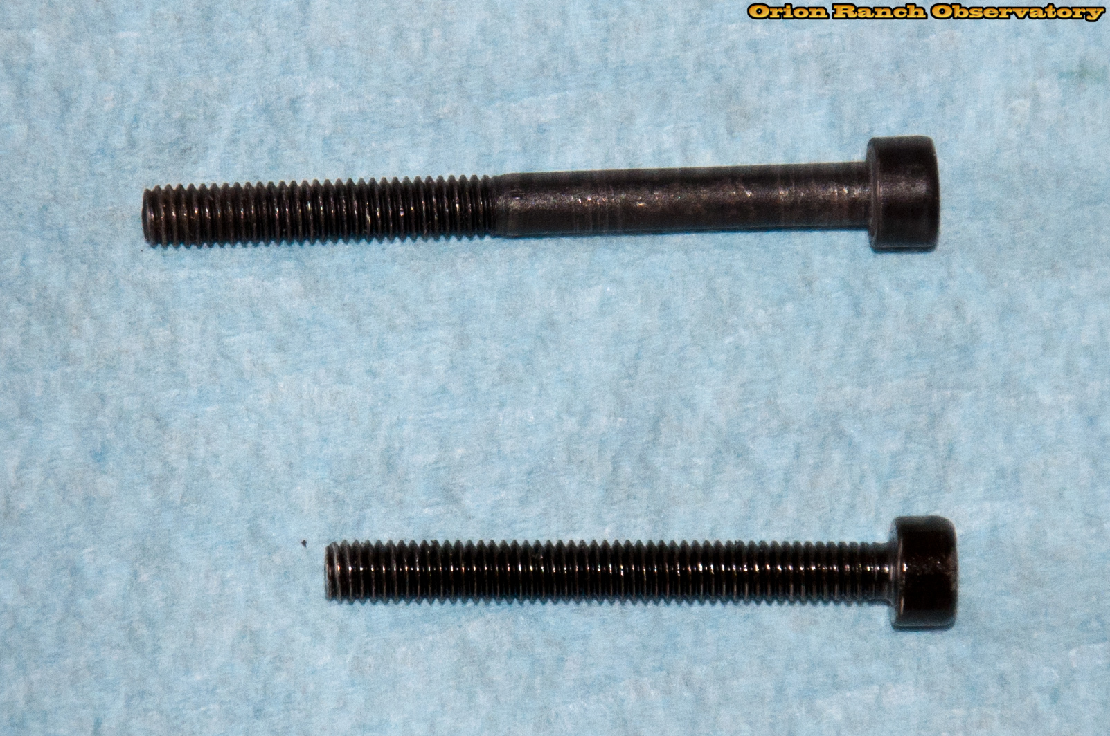
Six screws, four short and two longer ones up near the OTA, hold the plastic outer cover from the inside.
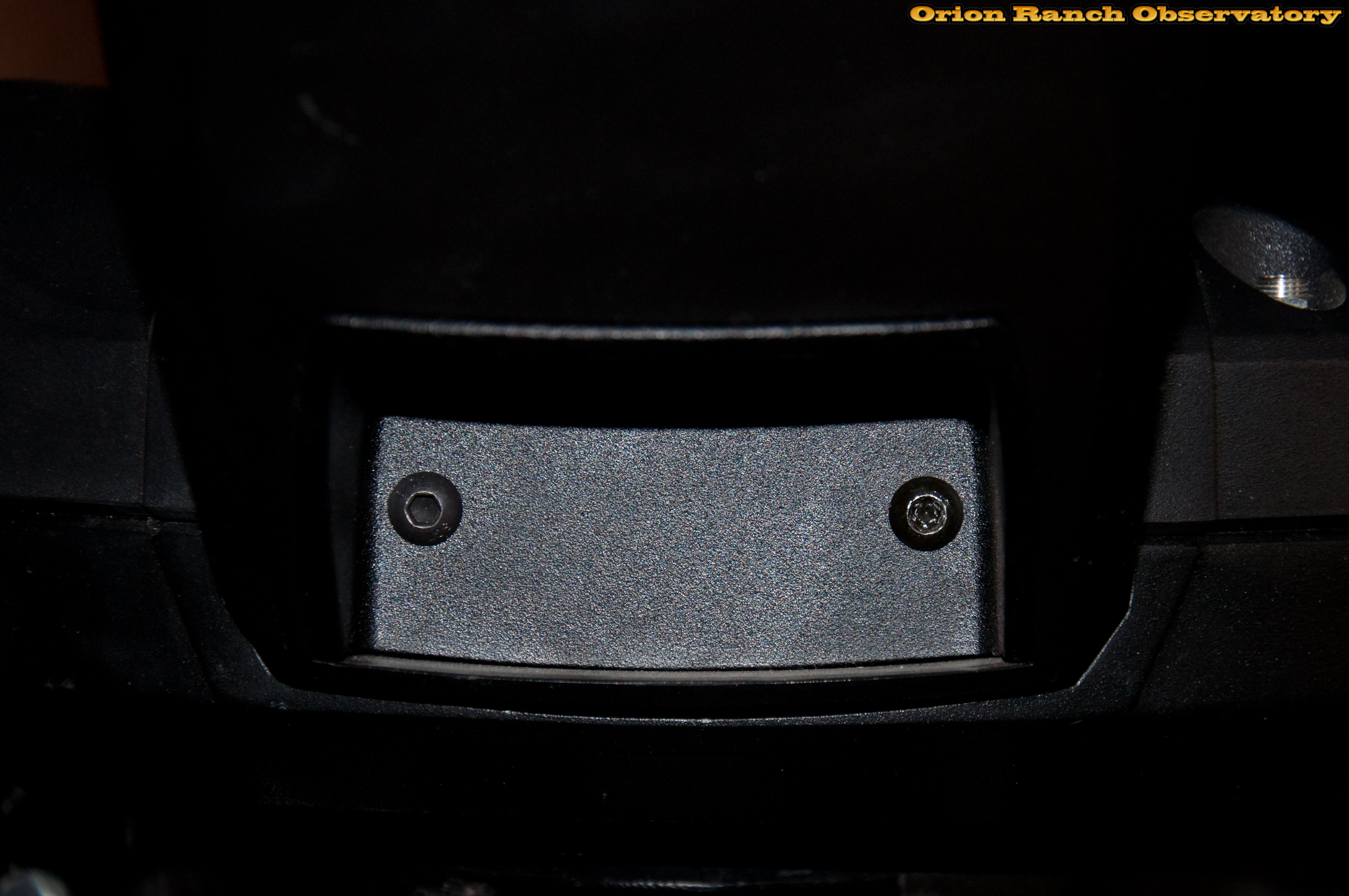
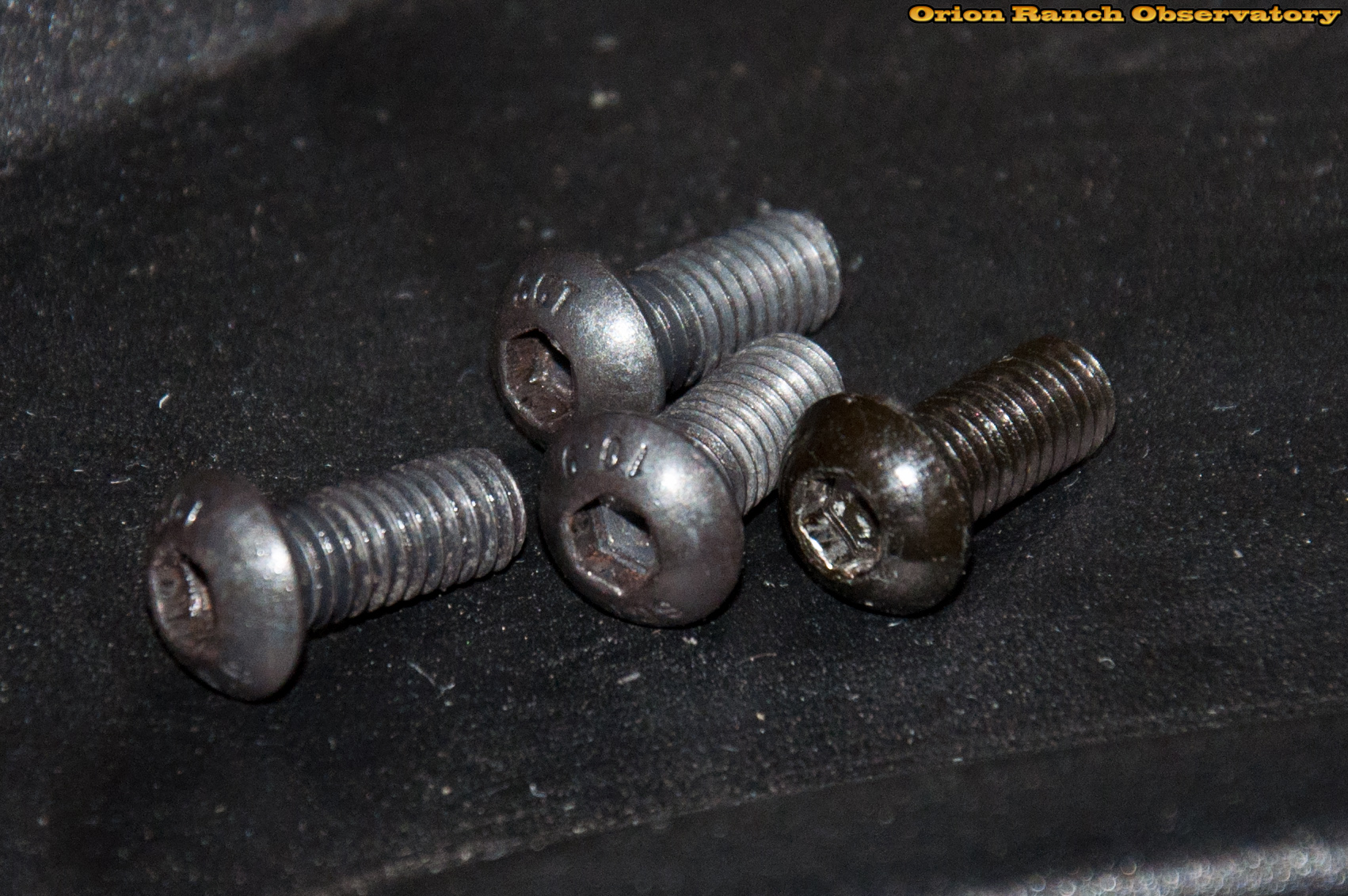
Four larger screws hold the metal handle insert to the aluminum frame. All ten screws must be removed to take off the cover. Ideally, these four would be removed first. First two:
Oops, two more!
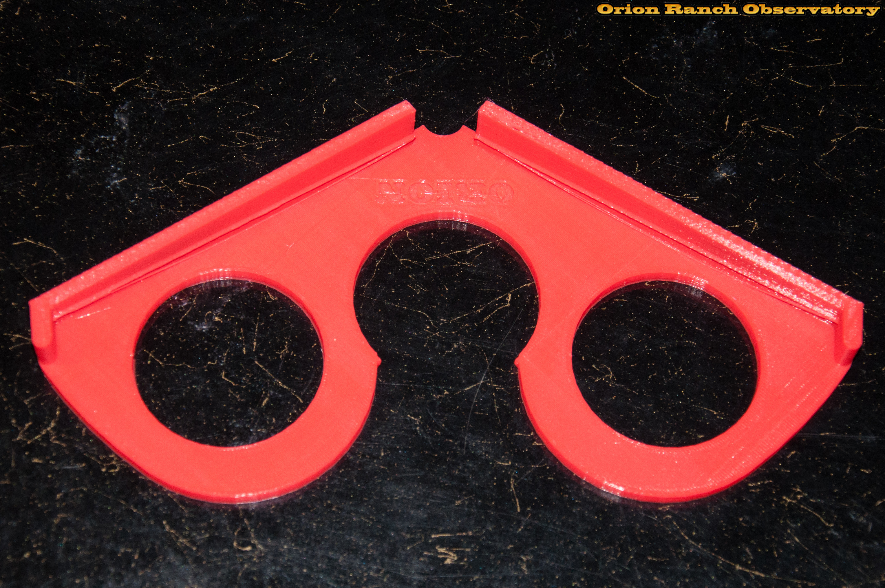
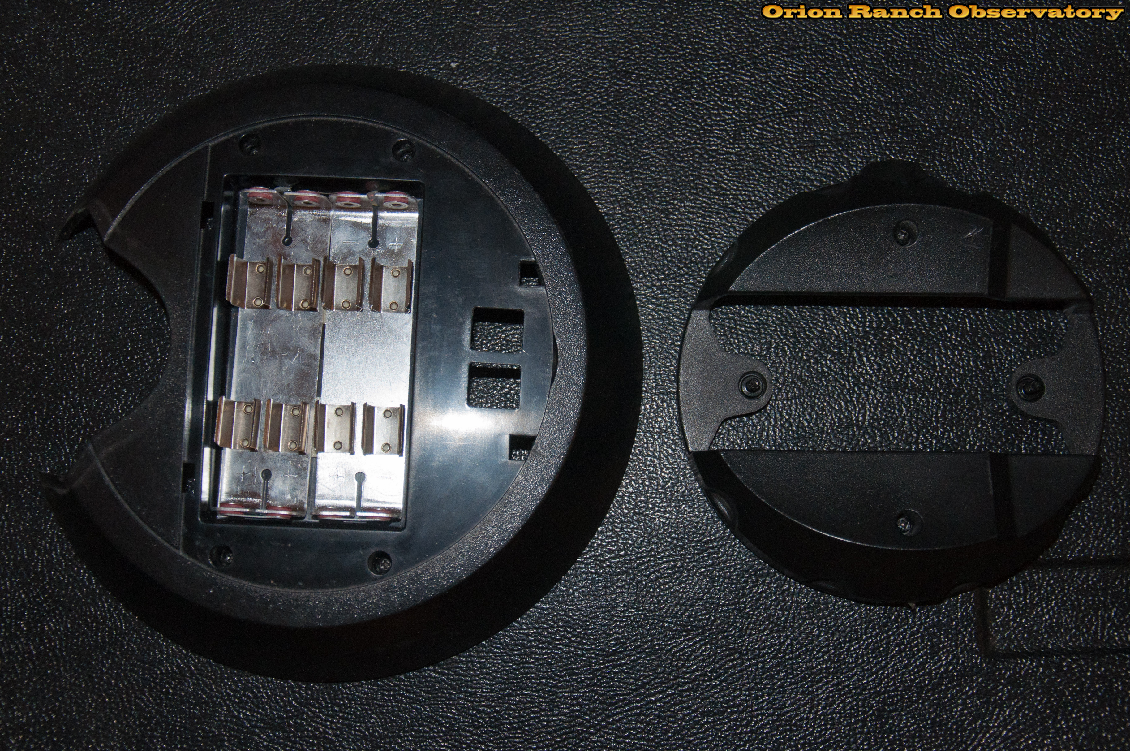
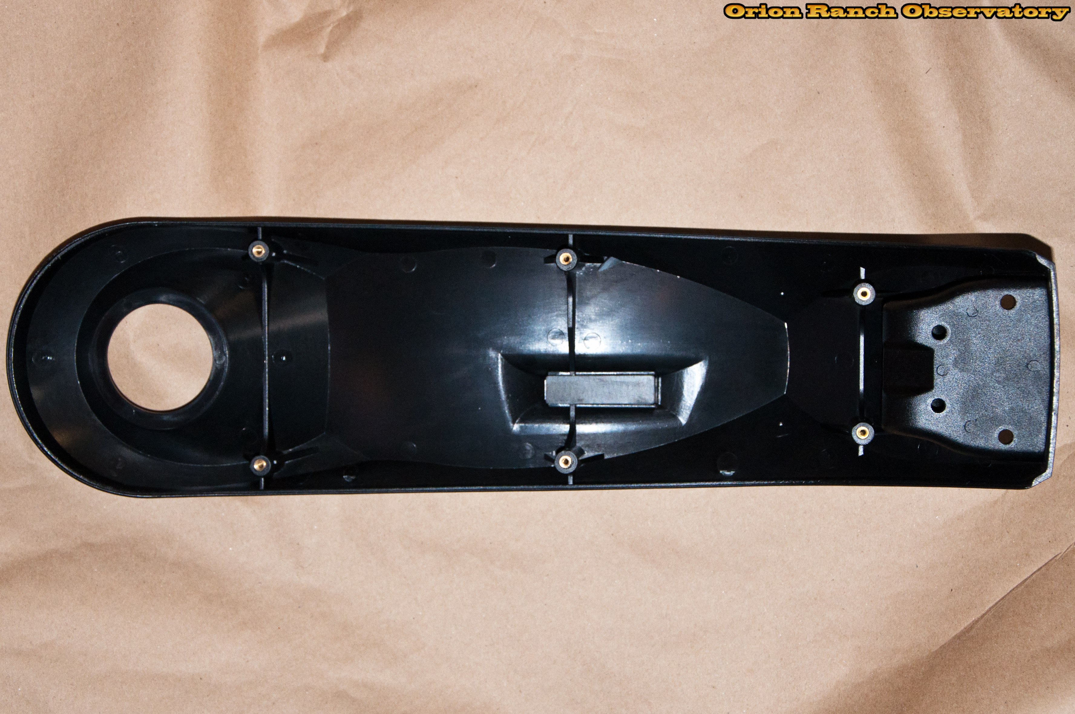
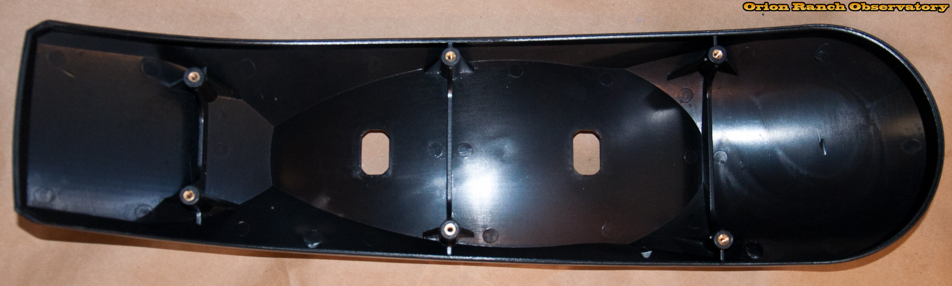
There’s the inside view of the plastic outer cover and bottom handle.
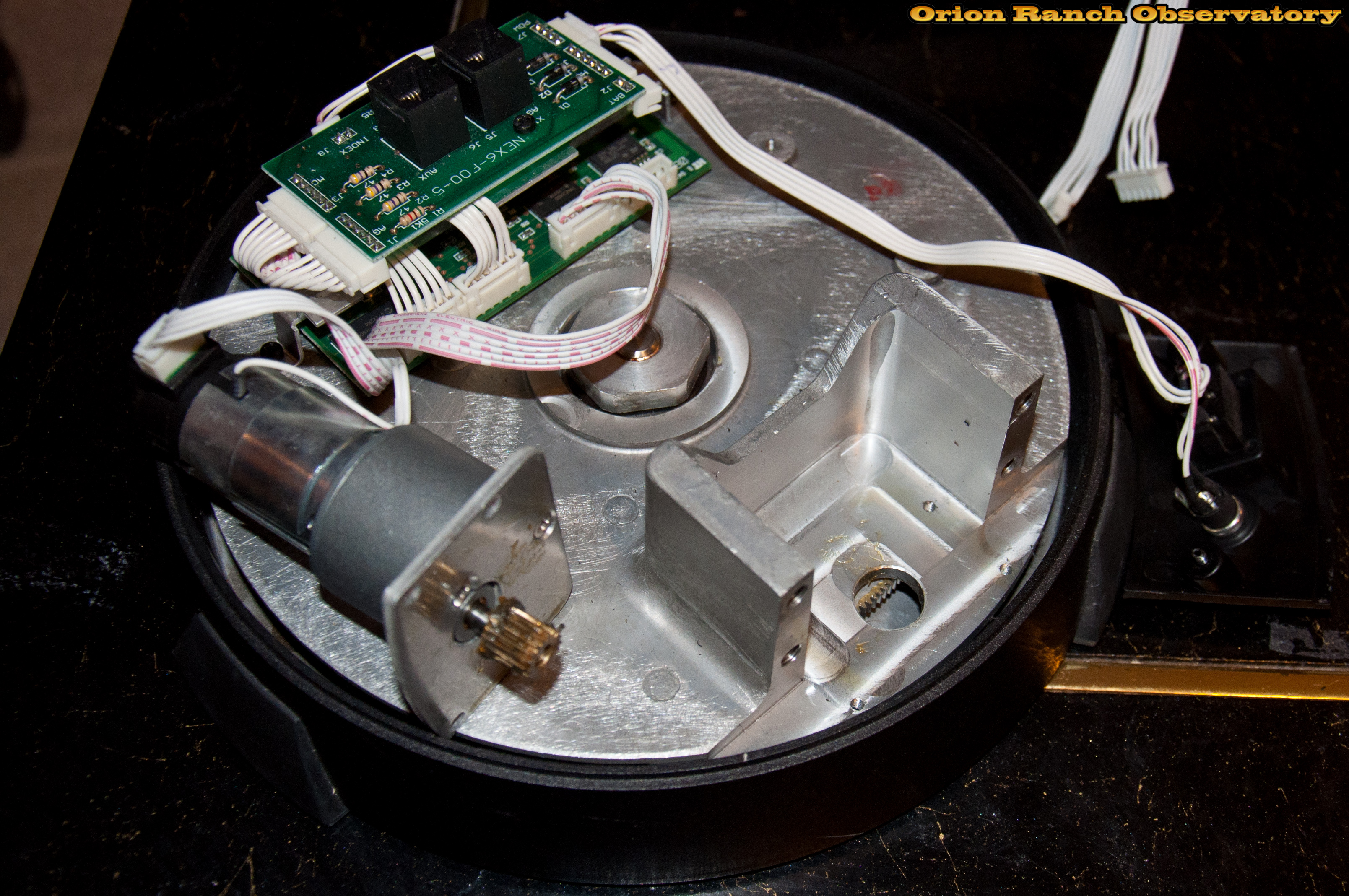
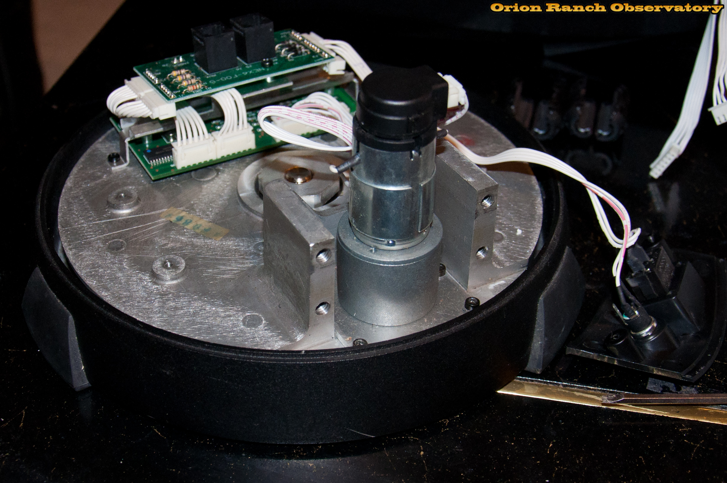
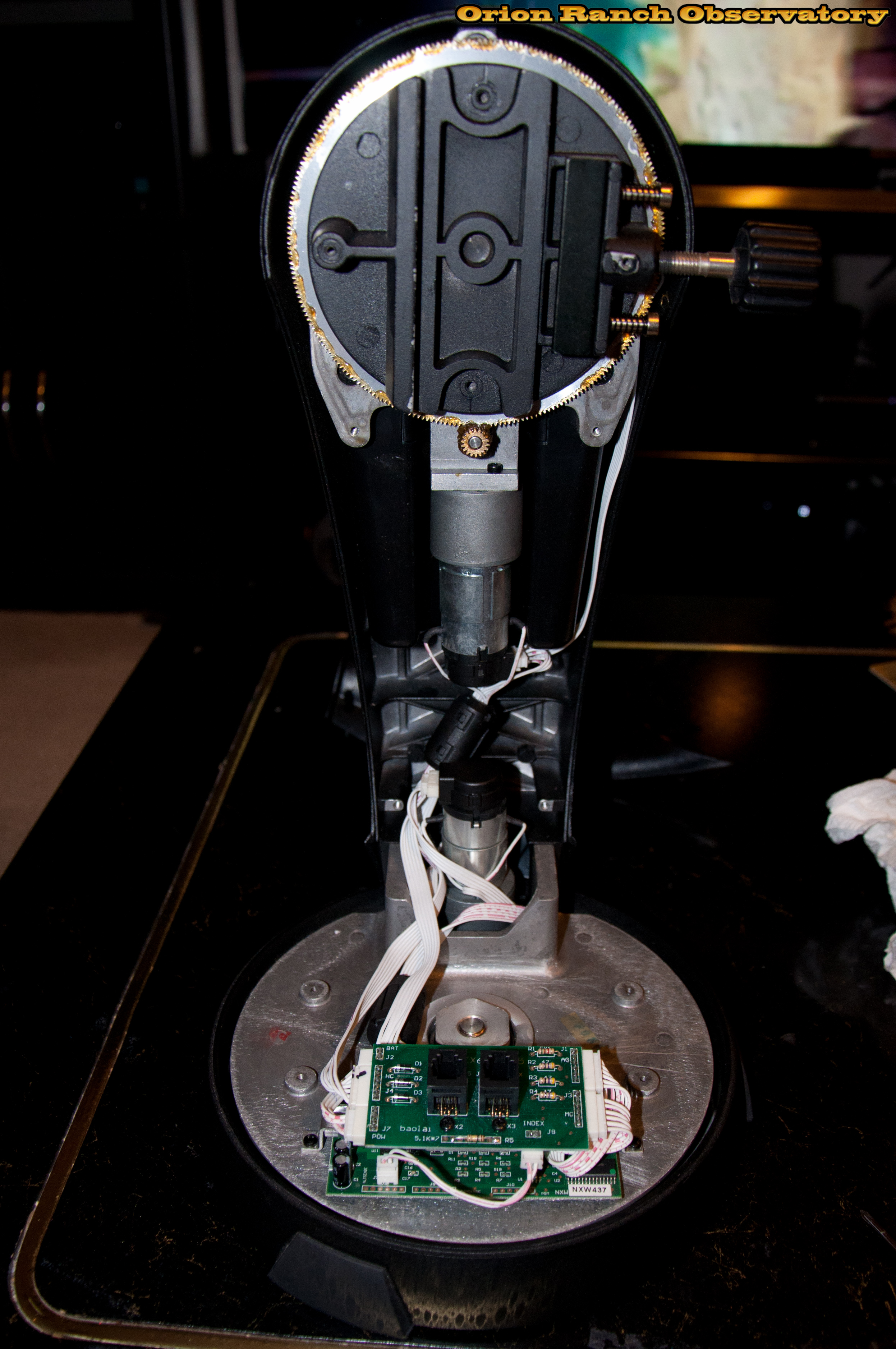
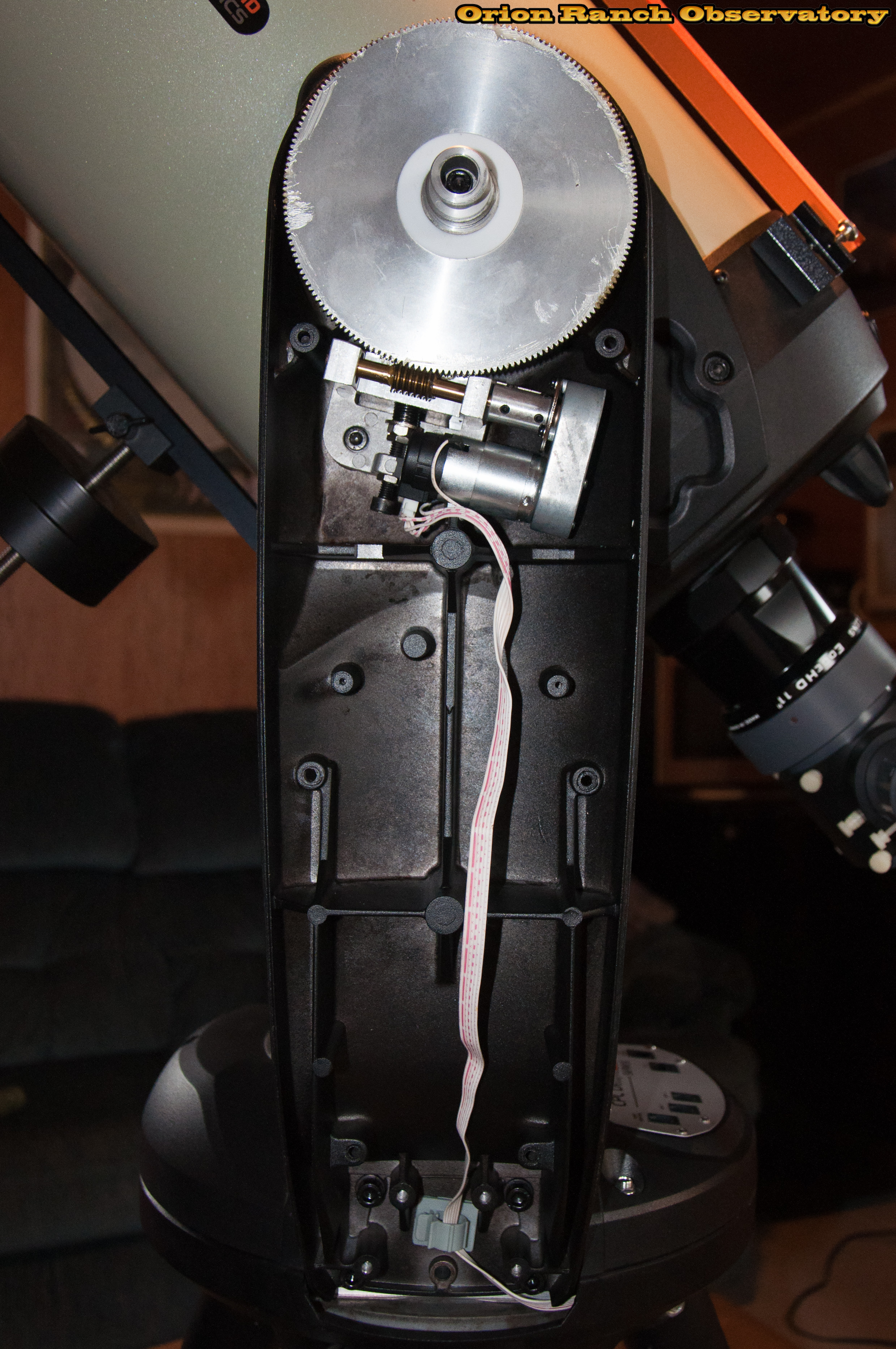
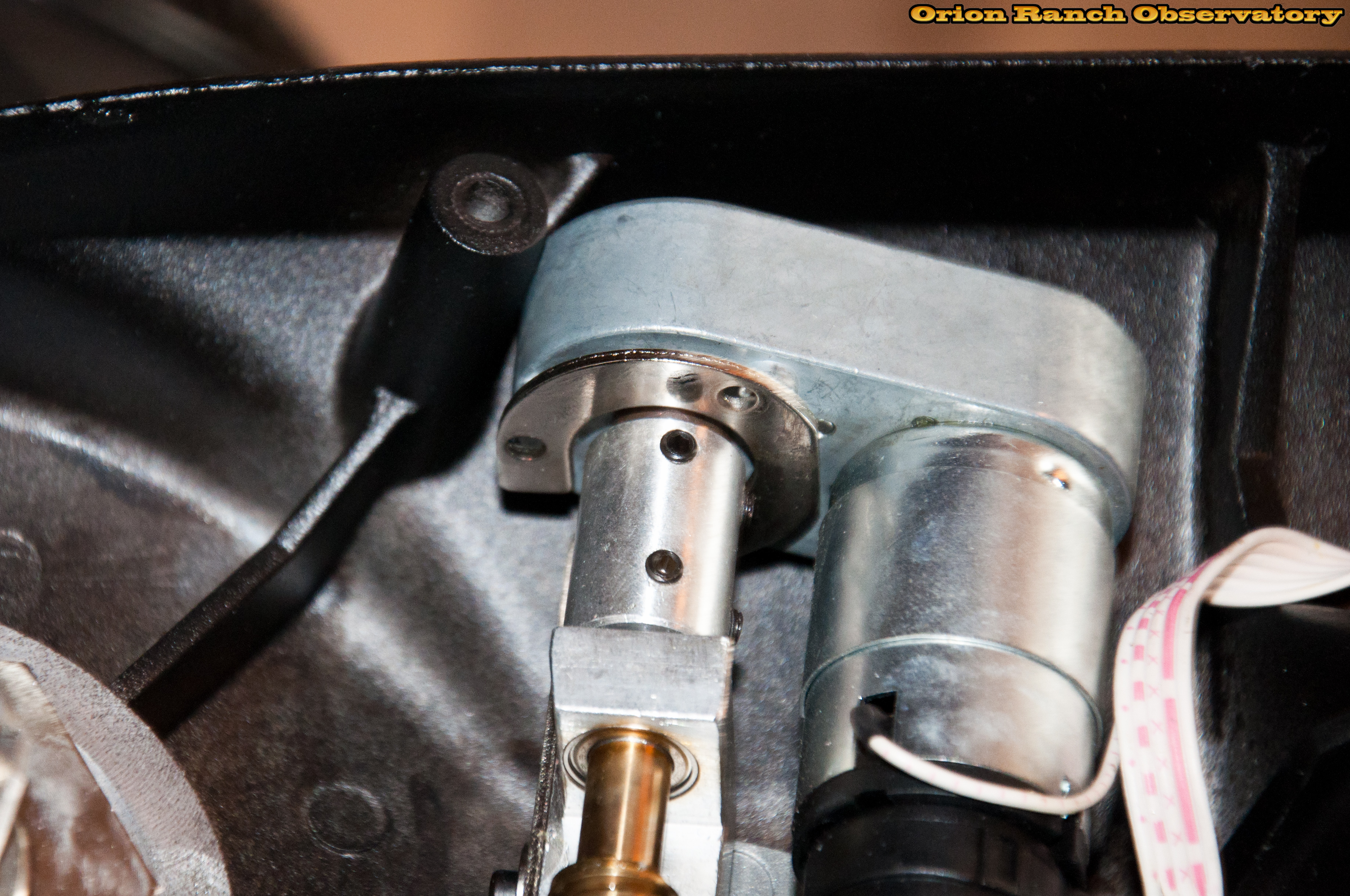
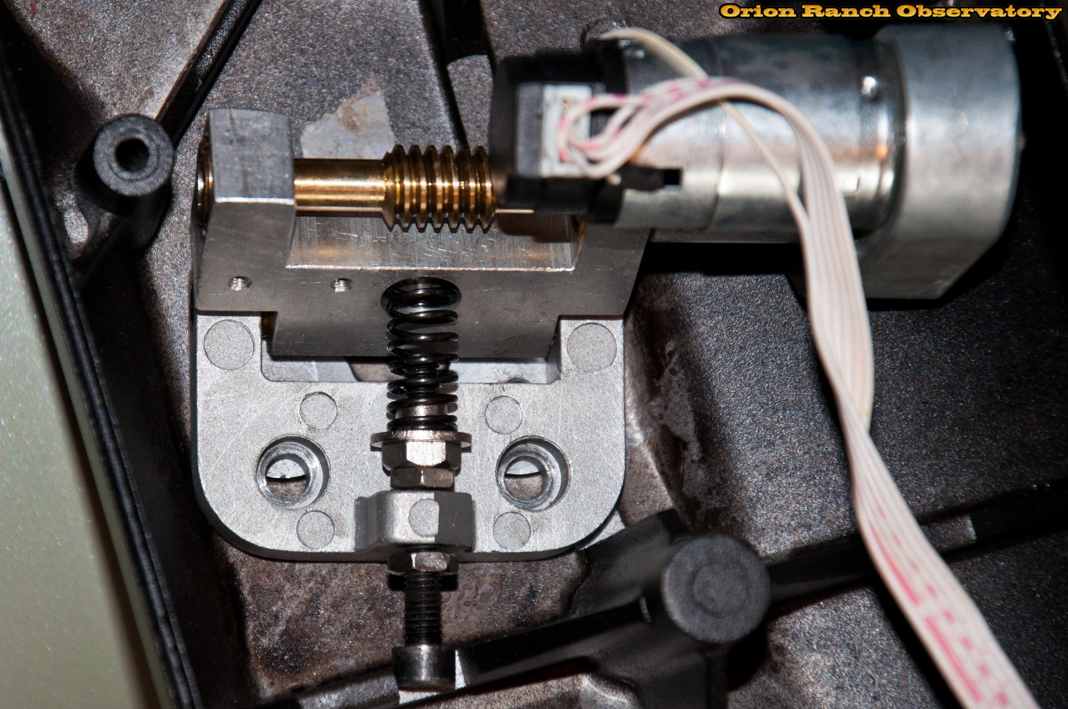
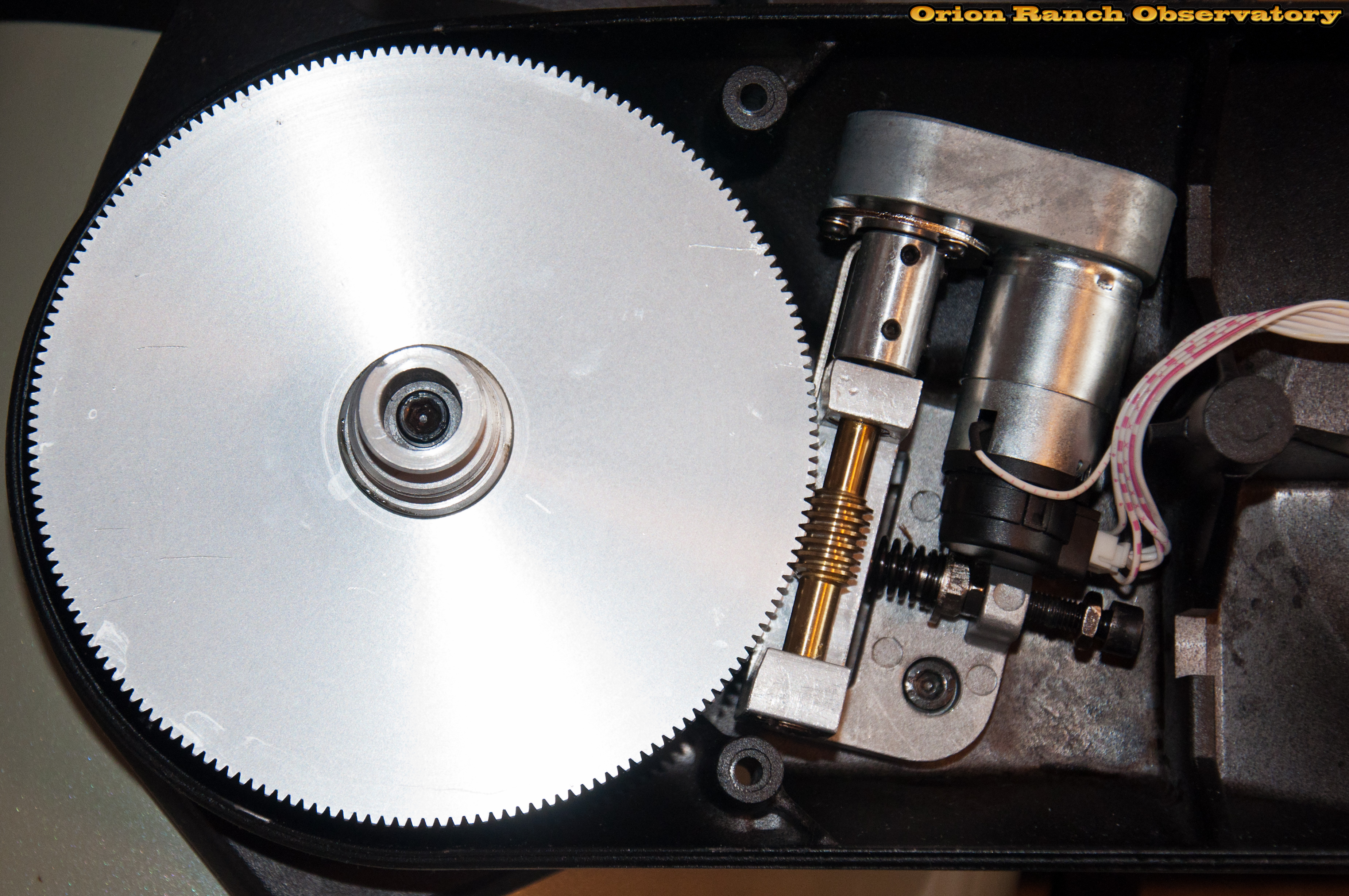
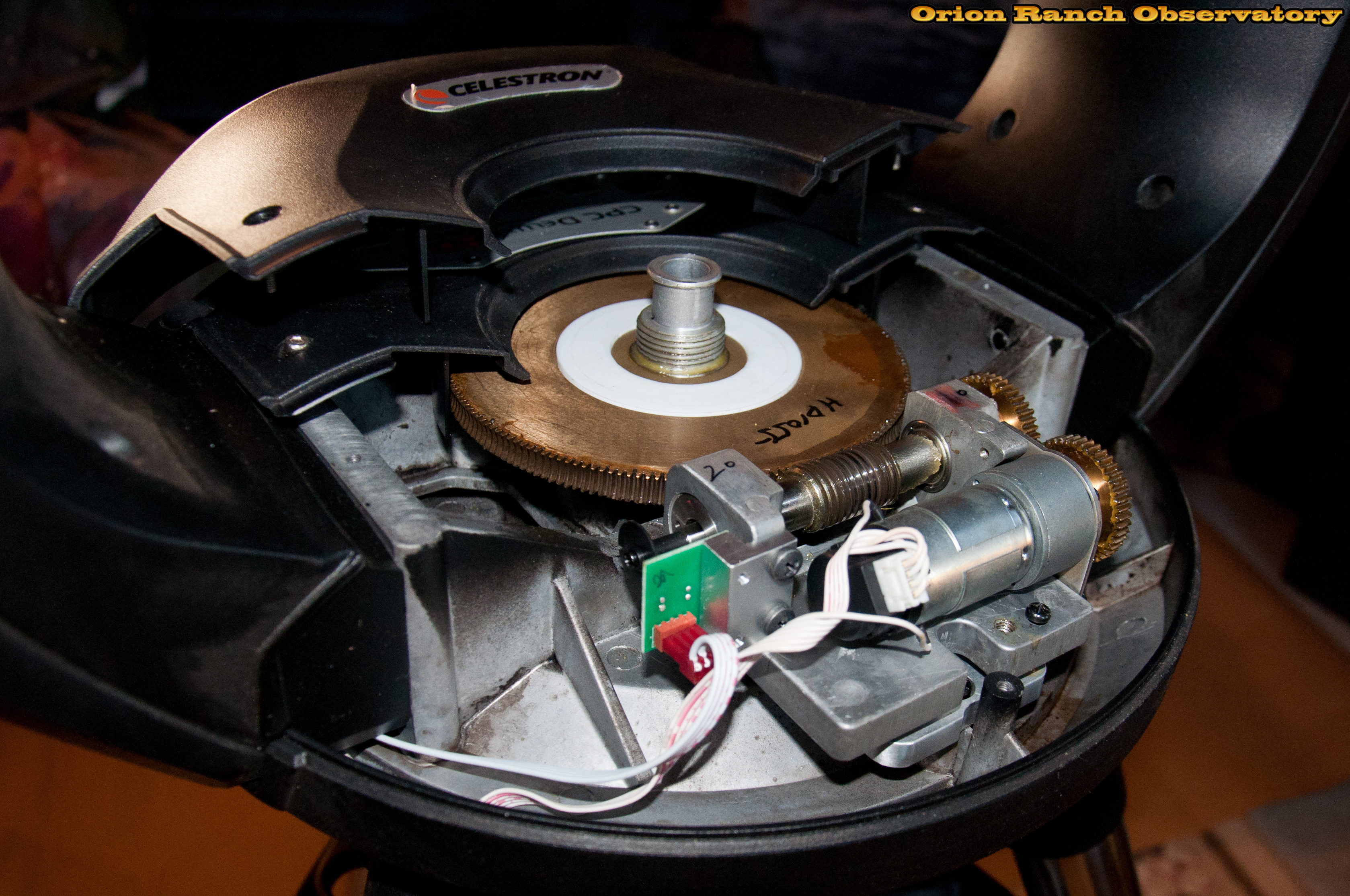
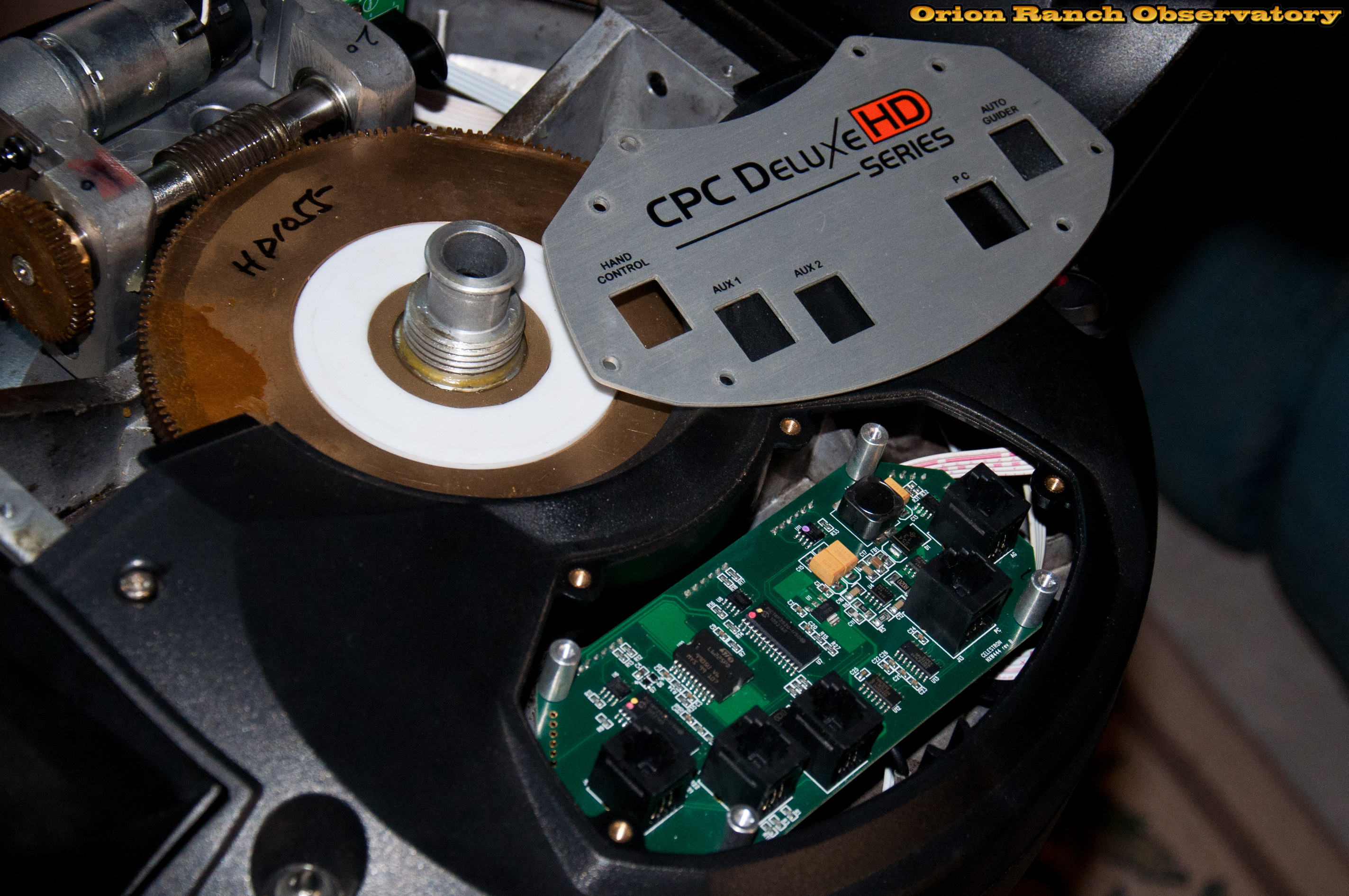
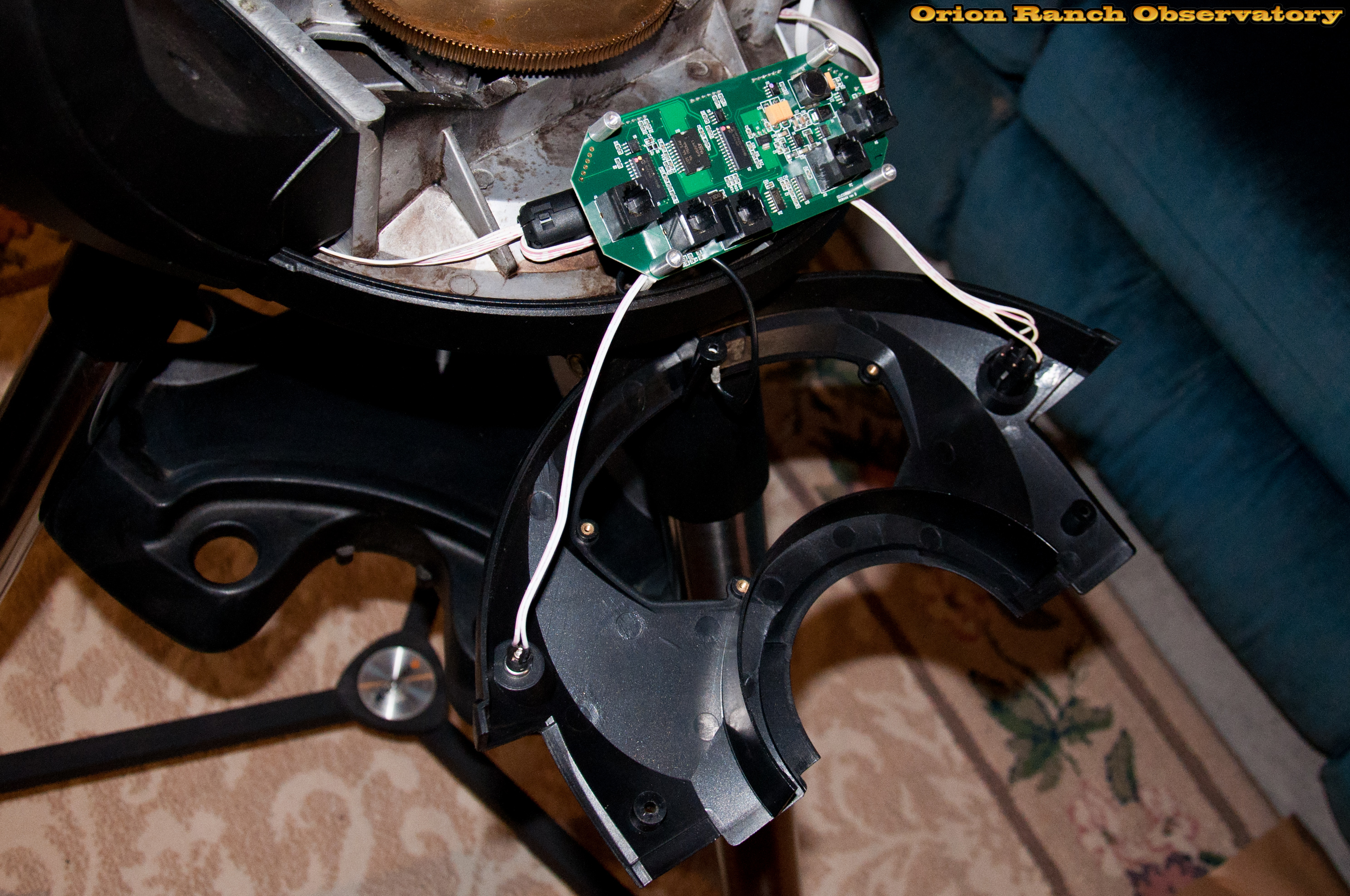
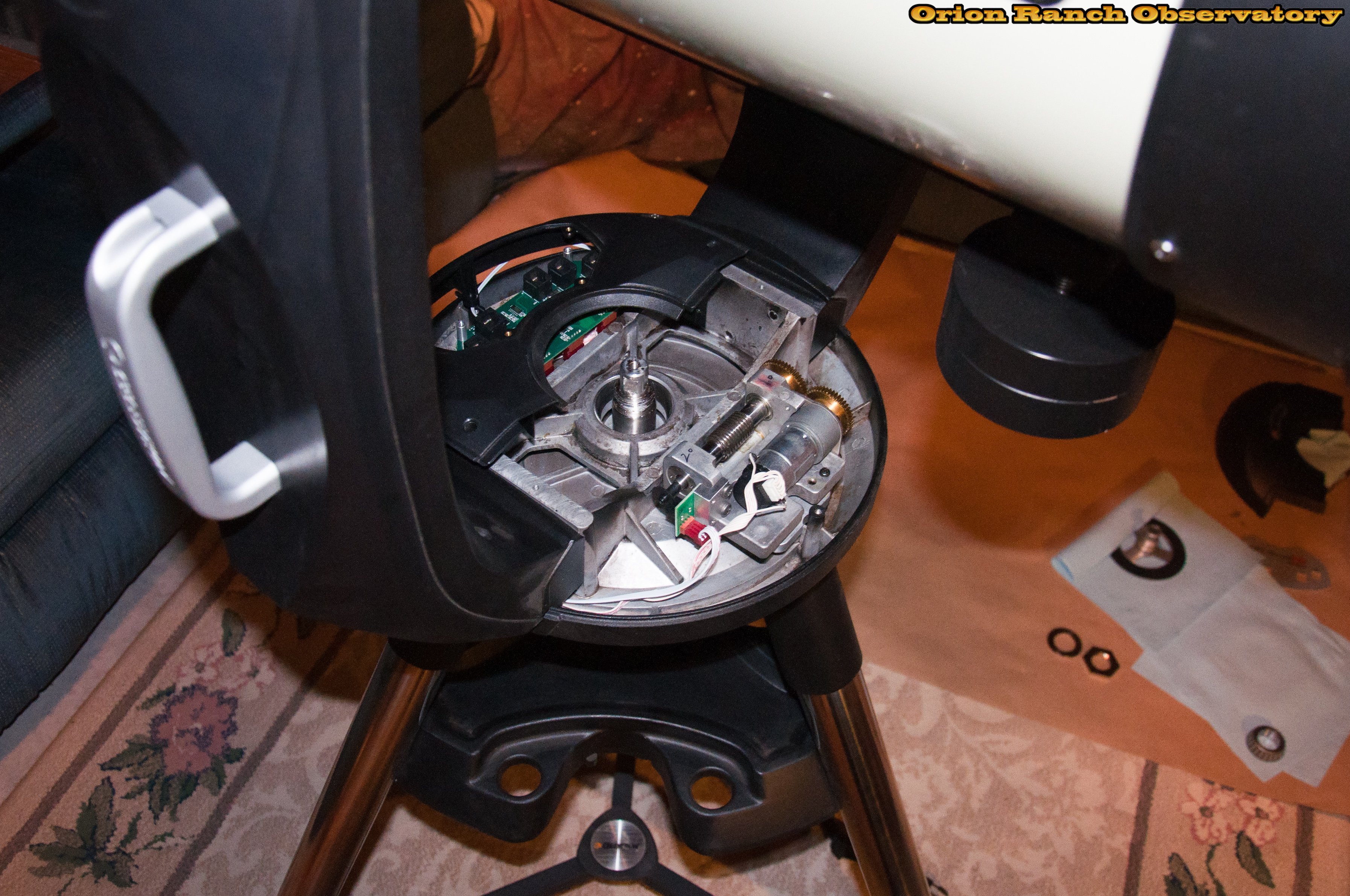
And a shot inside the drive fork assembly, showing the servo motor, gearbox, and worm gear.
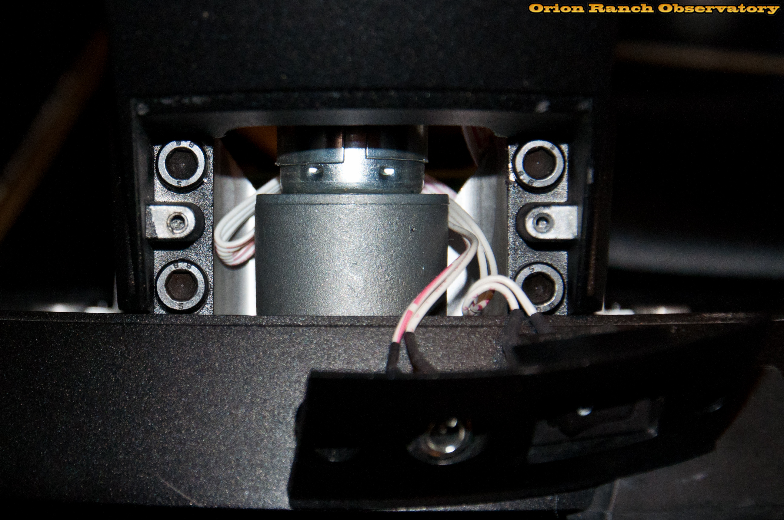
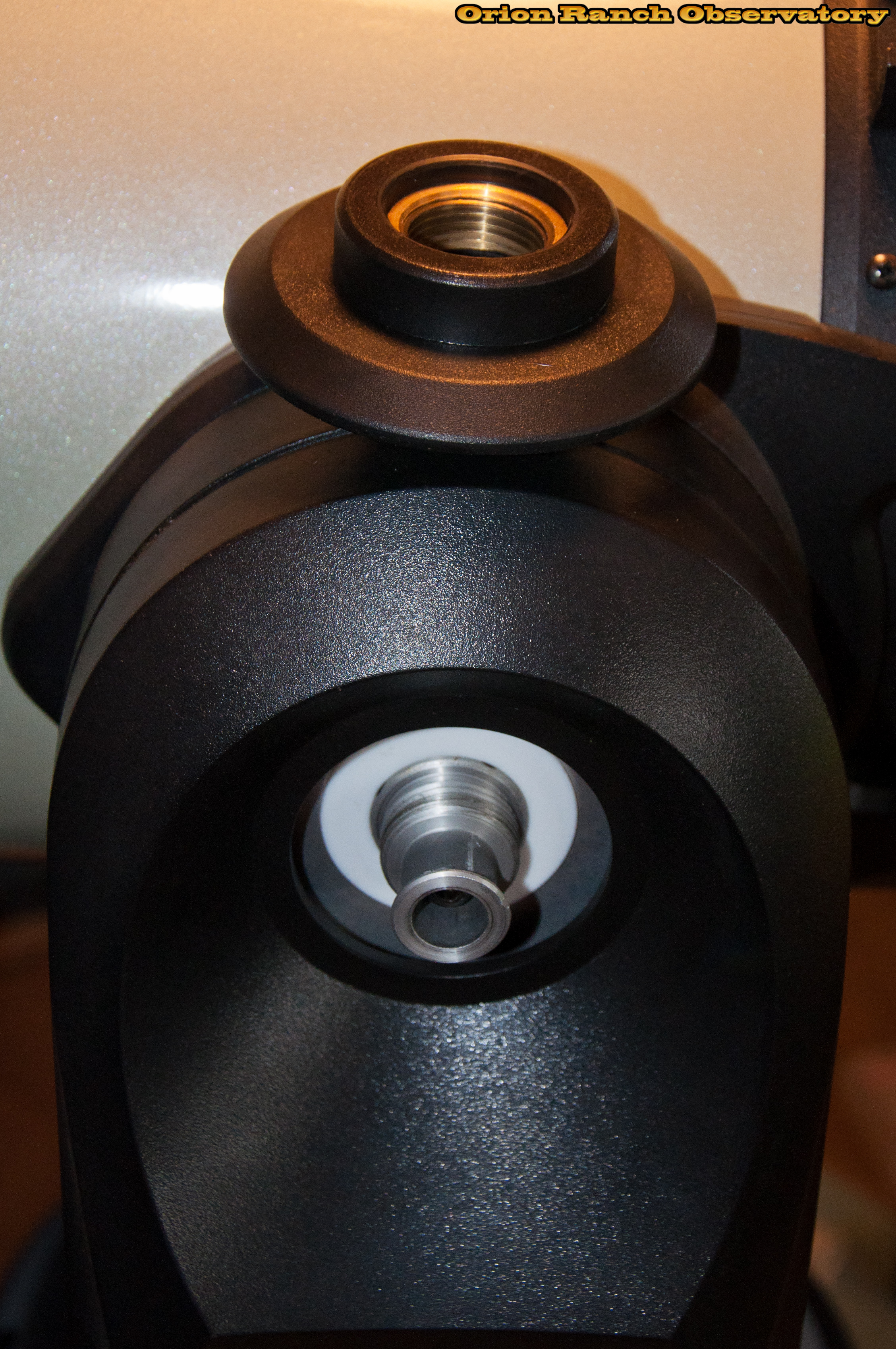
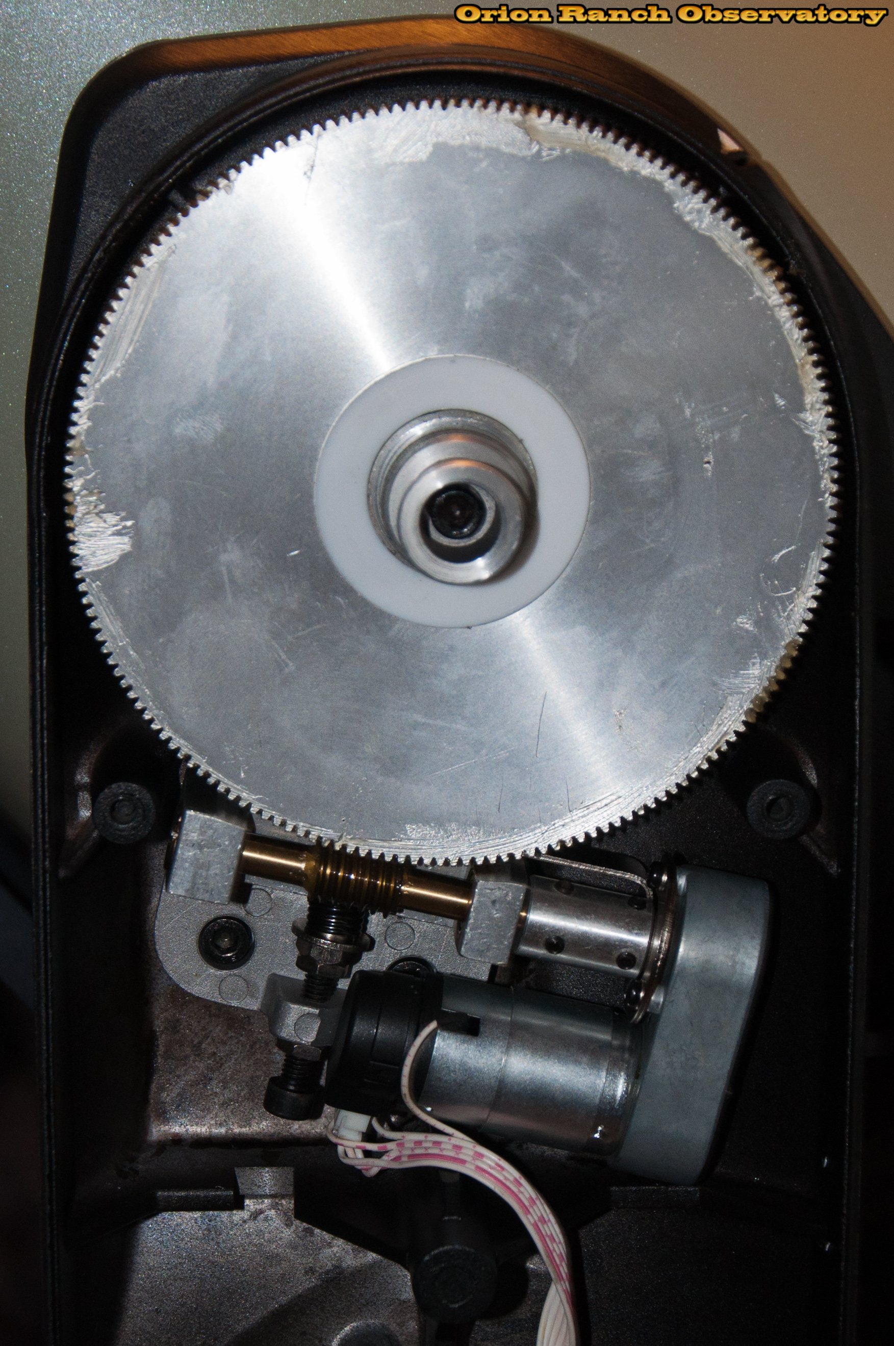
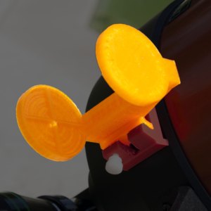
Here’s a close-up of the worm gear and drive unit. The drive looks similar to the azimuth drive, but the main aluminum worm gear is obviously smaller than the brass one in the base.
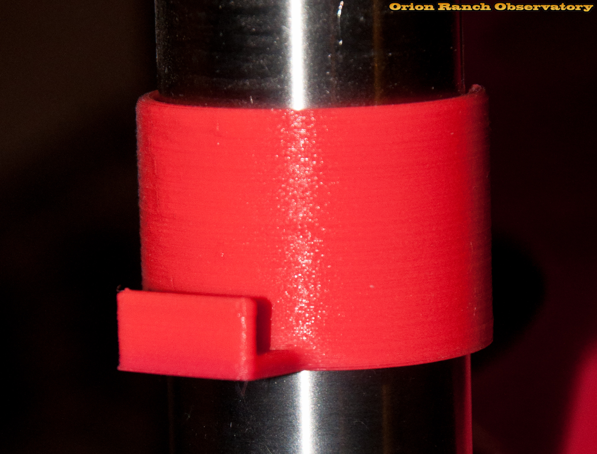
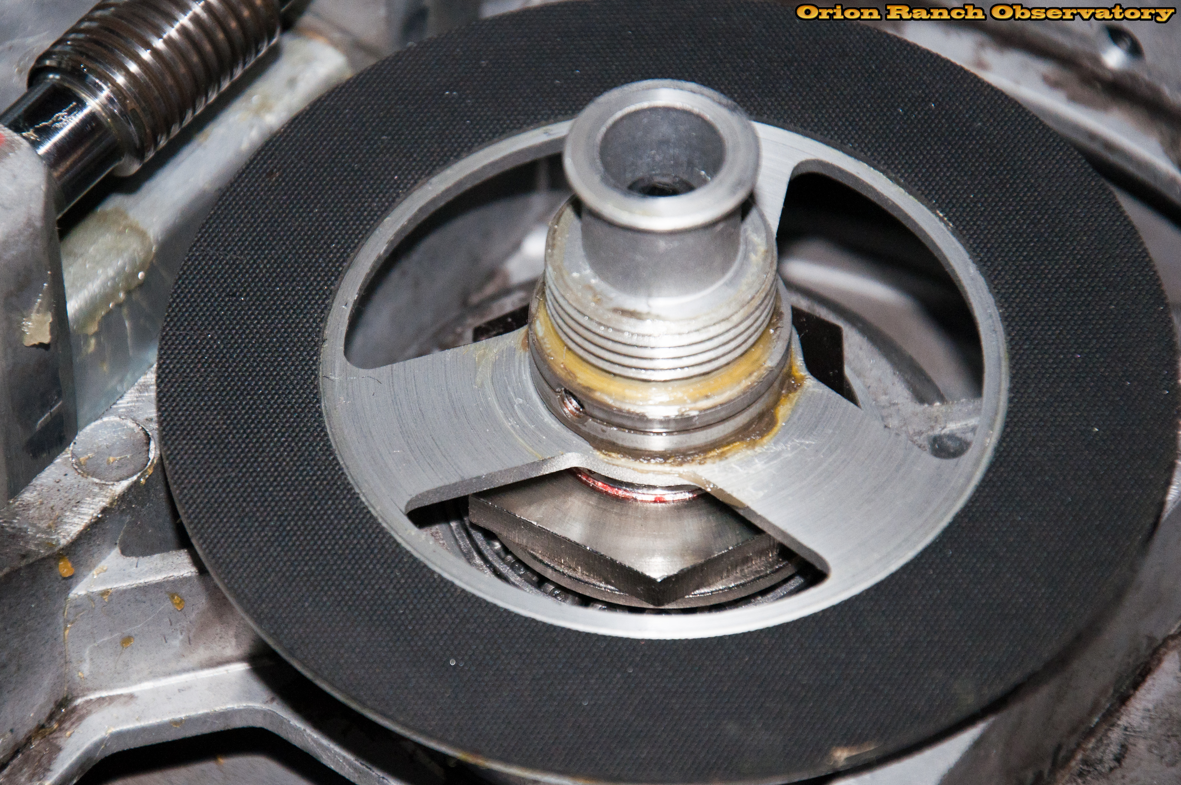
After slipping the main worm gear off the clutch plate, you can see the rubber sheet on an aluminum assembly that appears identical to the azimuth axis clutch plate. Note the Allen wrench tool being used as a spacer to keep the spring loaded worm from hitting the clutch and getting grease on it.
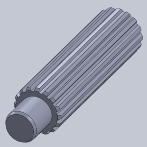
The declination/elevation axis worm gear is just a simple aluminum part with no additional features. Not a great picture, but I’m not about to take things back apart to get a better one!
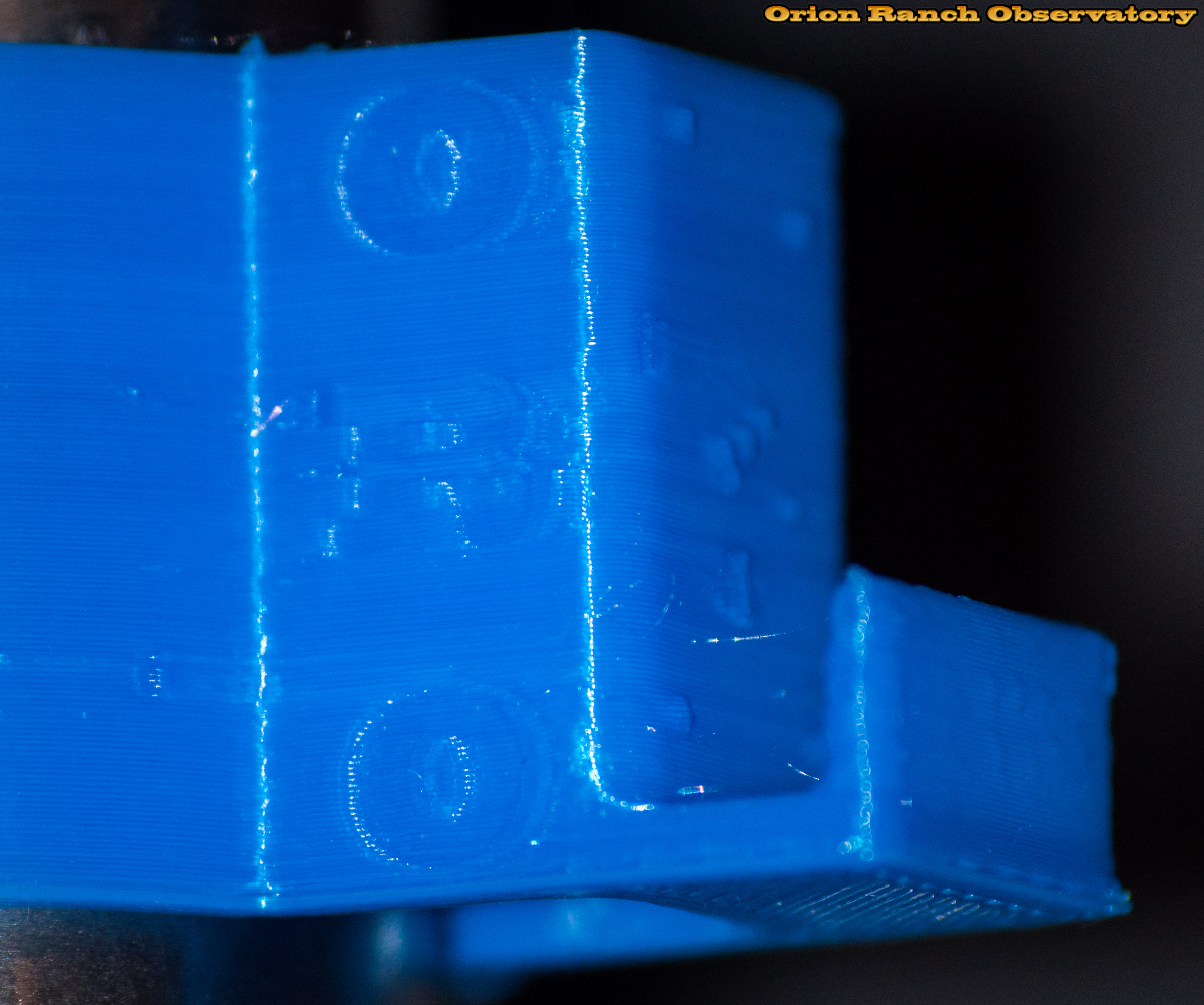
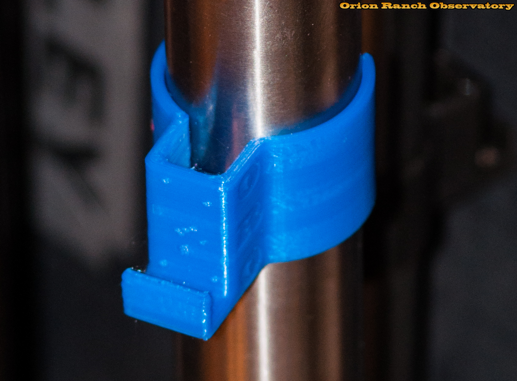
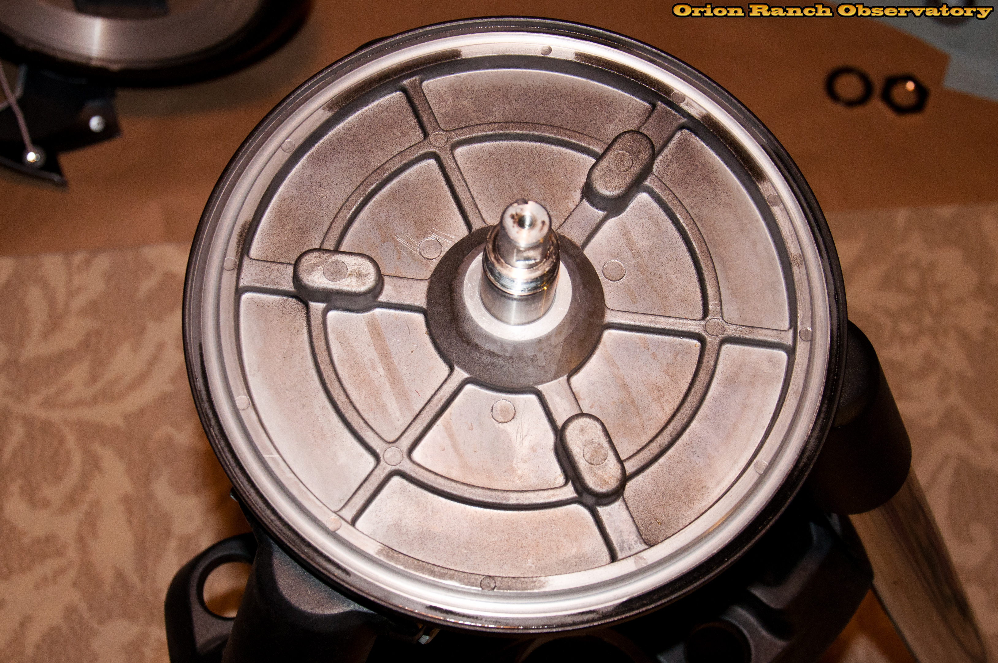
The declination/elevation axis has the same two flats and key for attaching the clutch plate.
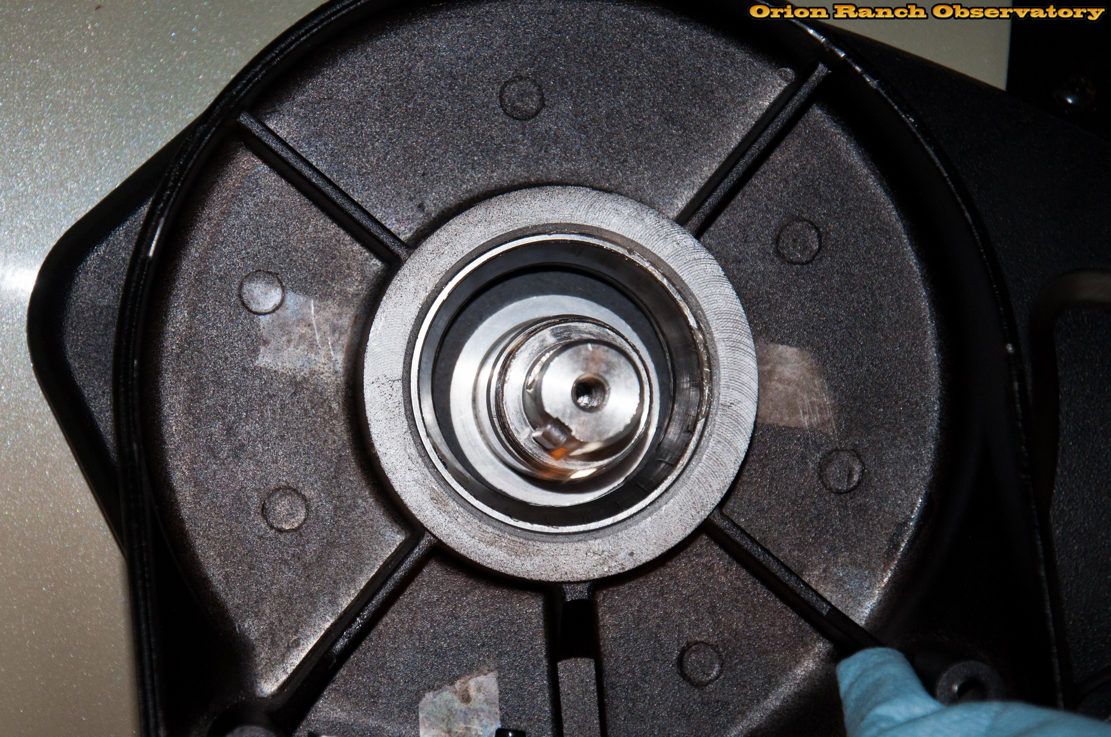
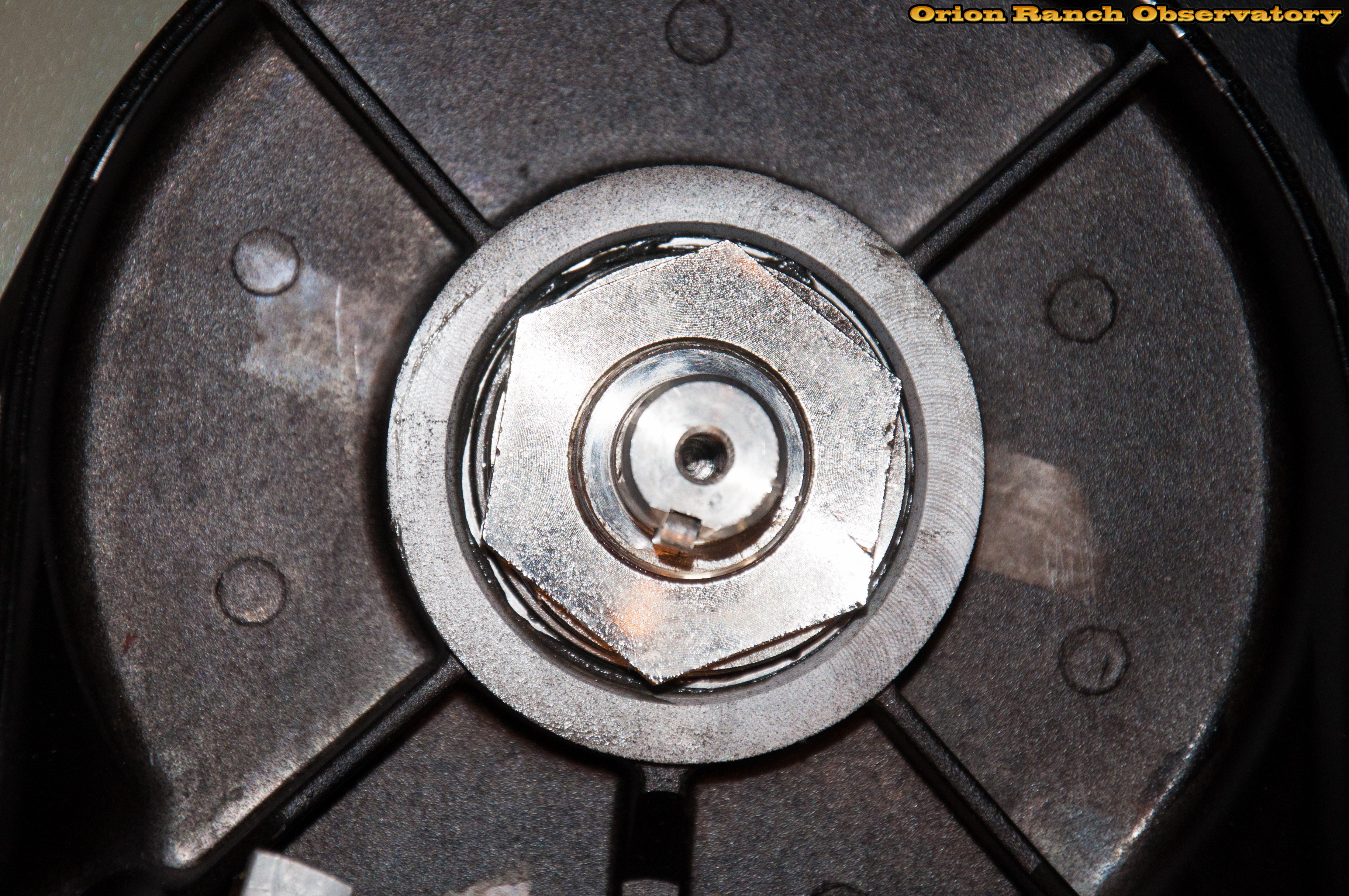
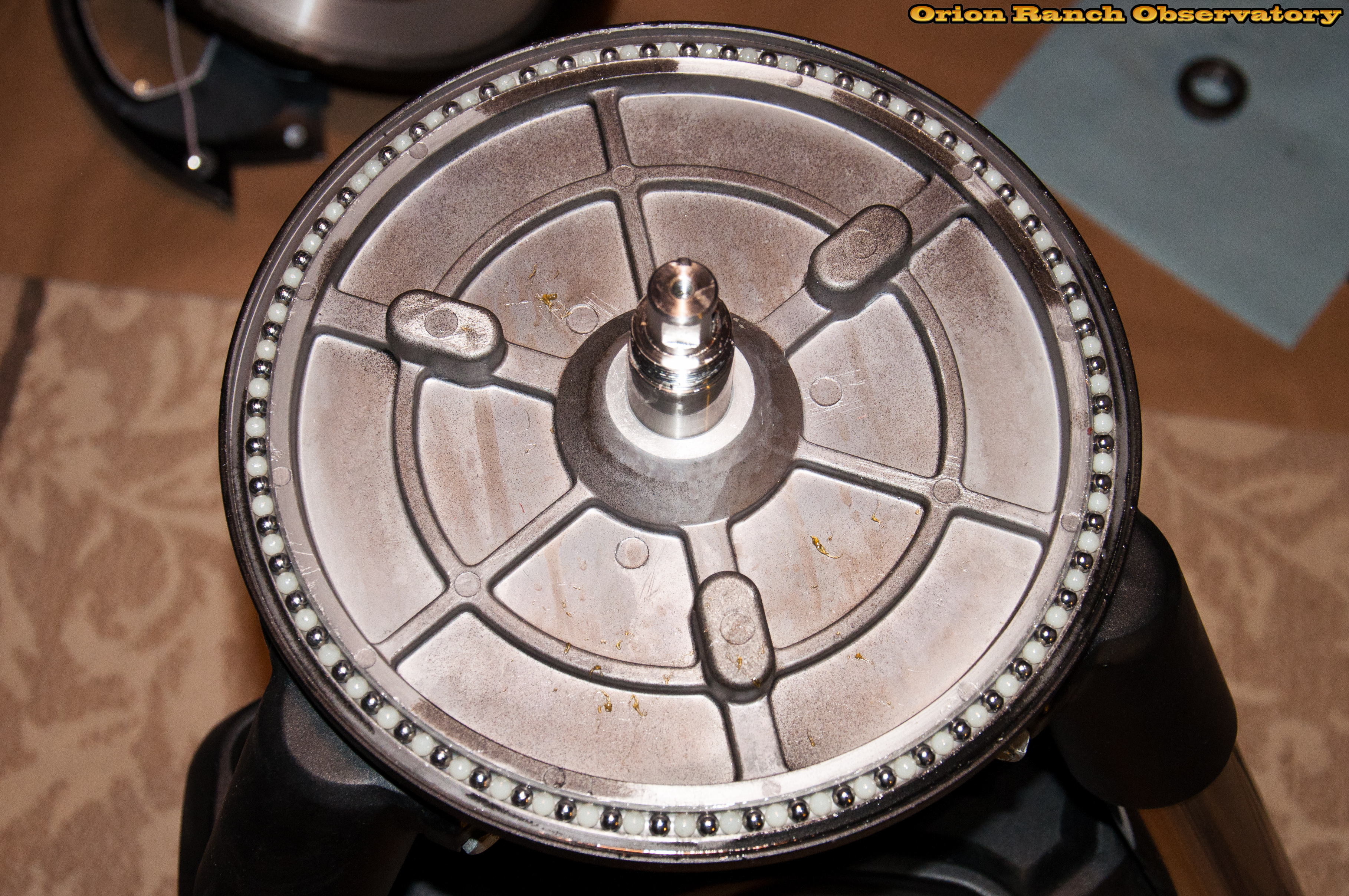
Close-up of clutch plate showing set screws and center socket head cap screw. Looks a lot like the azimuth axis clutch plate, doesn’t it?
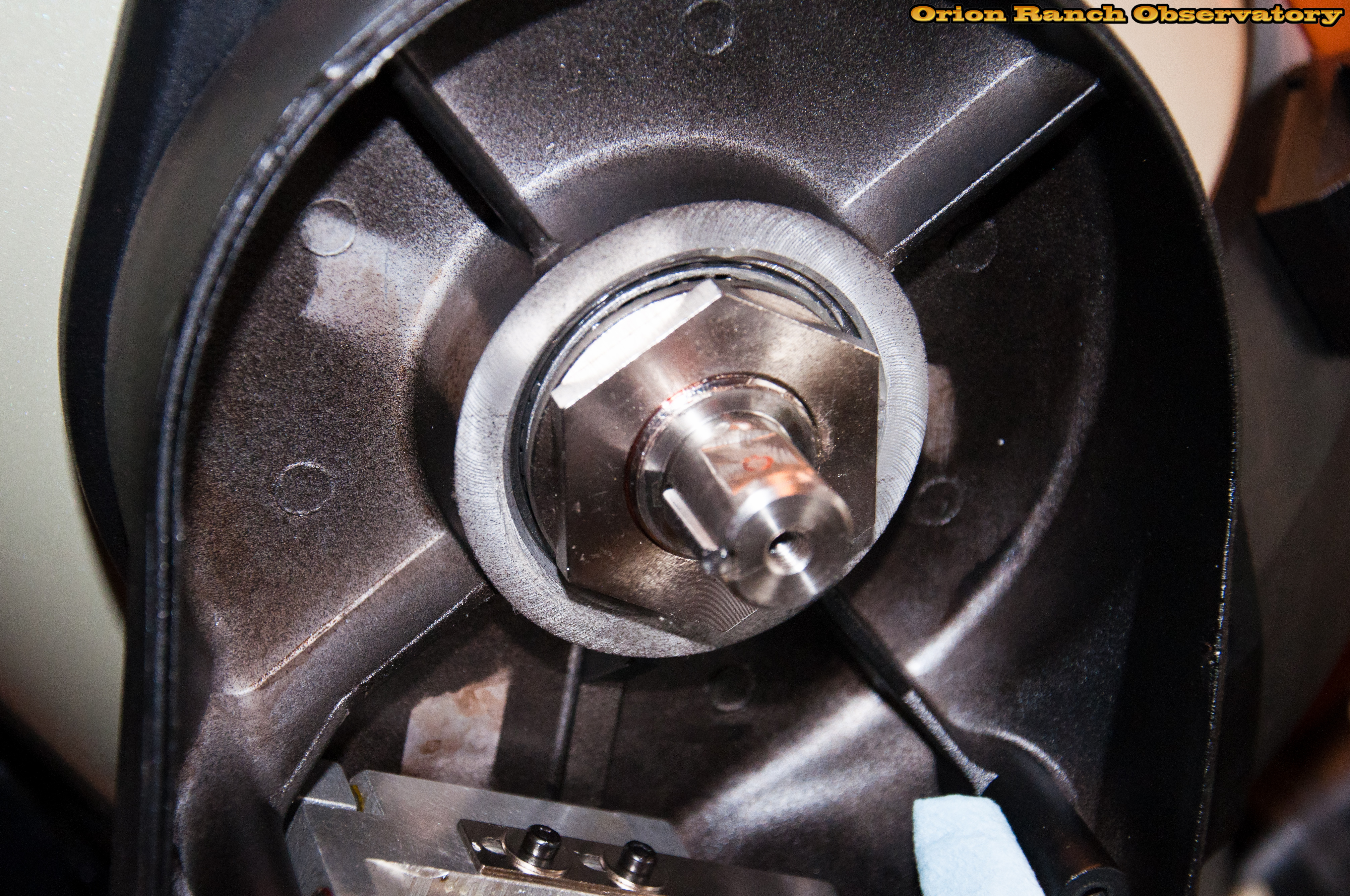
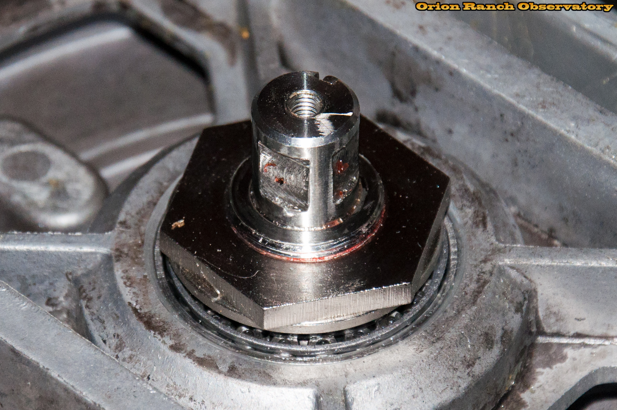
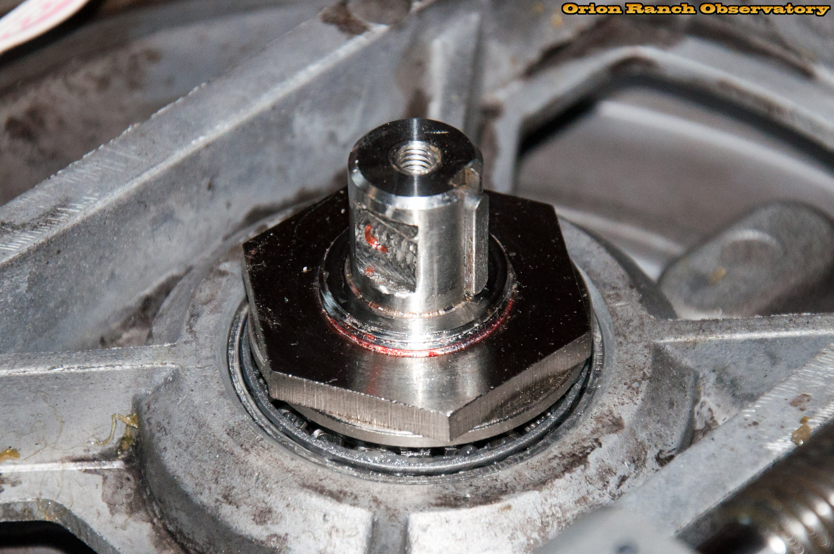
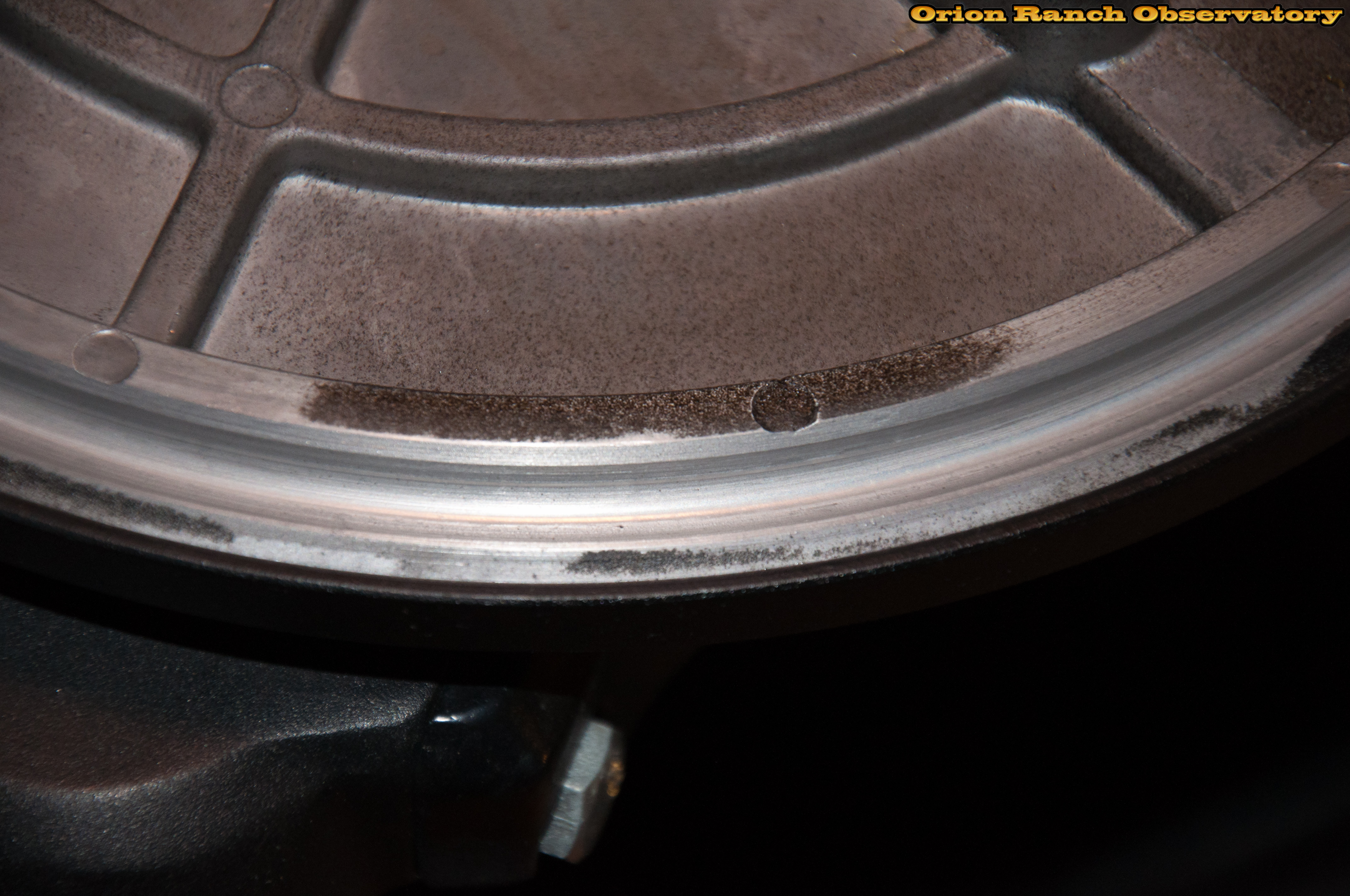
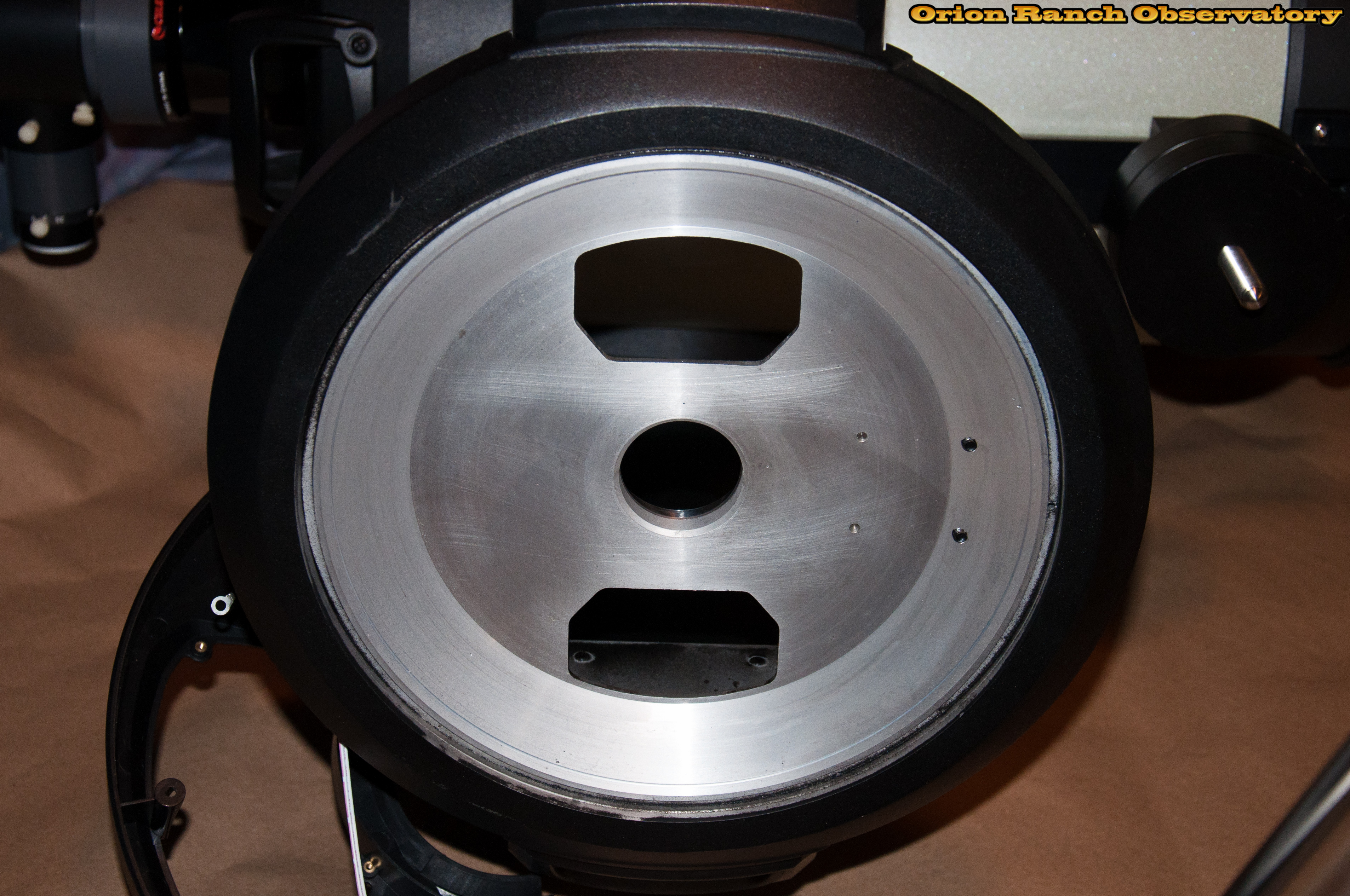
After removing the nut and washer, the same thrust bearing as the azimuth axis is visible.
After laying the scope on its side, declination axis pointing up to minimize stress, the bearing slips out easily.
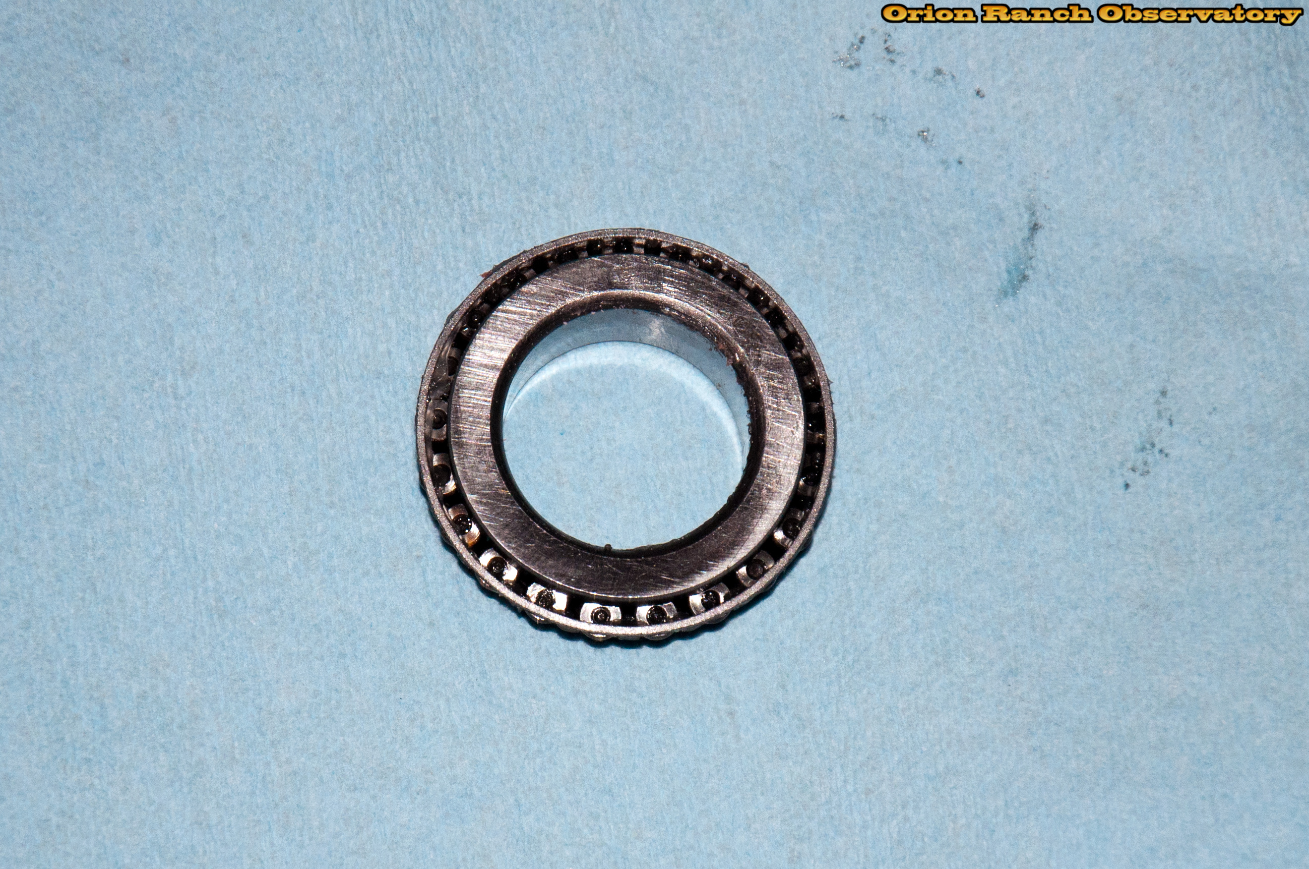
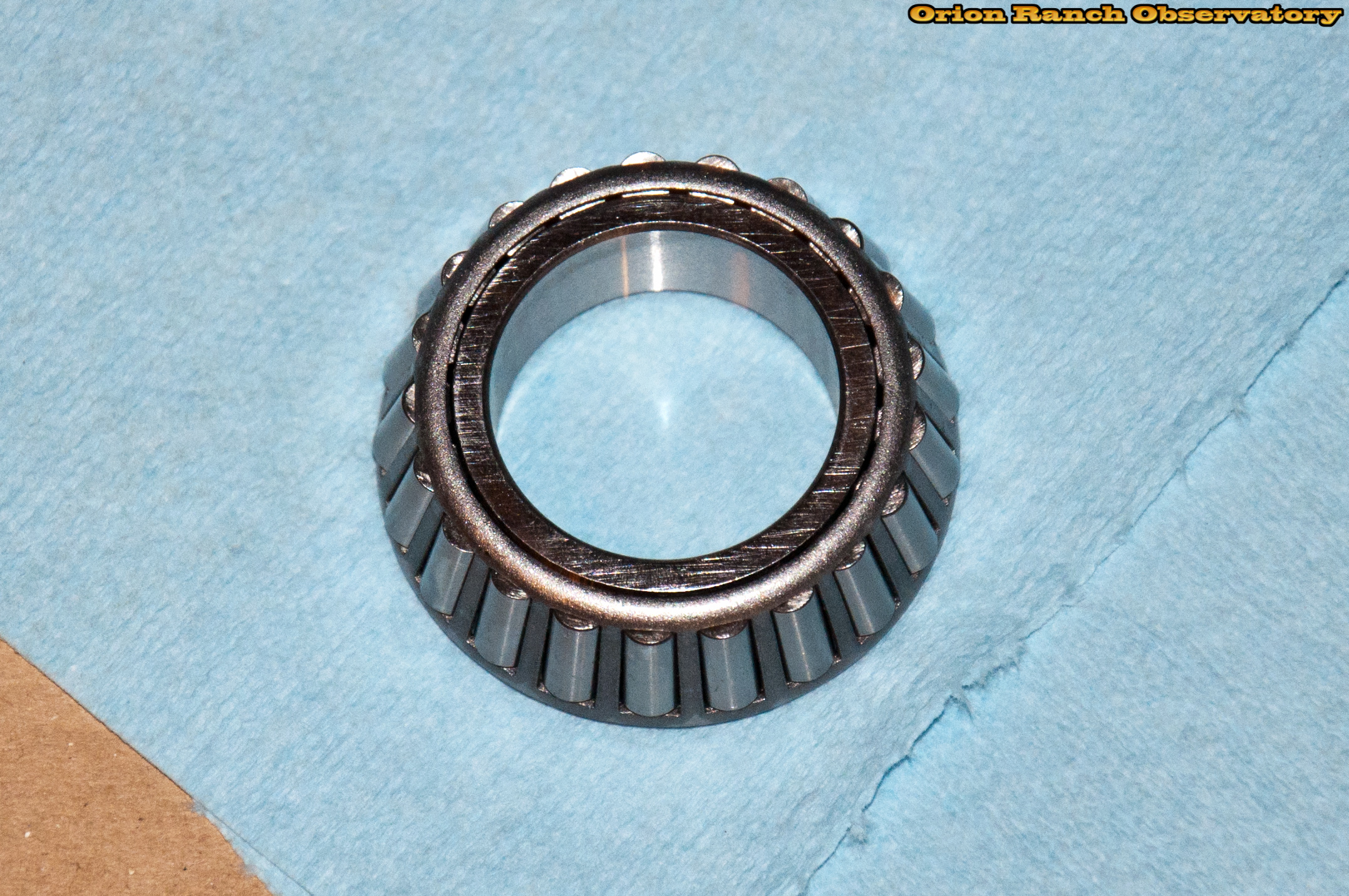
The removed thrust bearing. Again, this appears to be the same thrust bearing as the azimuth axis.
After cleaning and re-greasing the bearing it’s re-installed.
And finally re-installing the pressure nut and washer on the bearing.
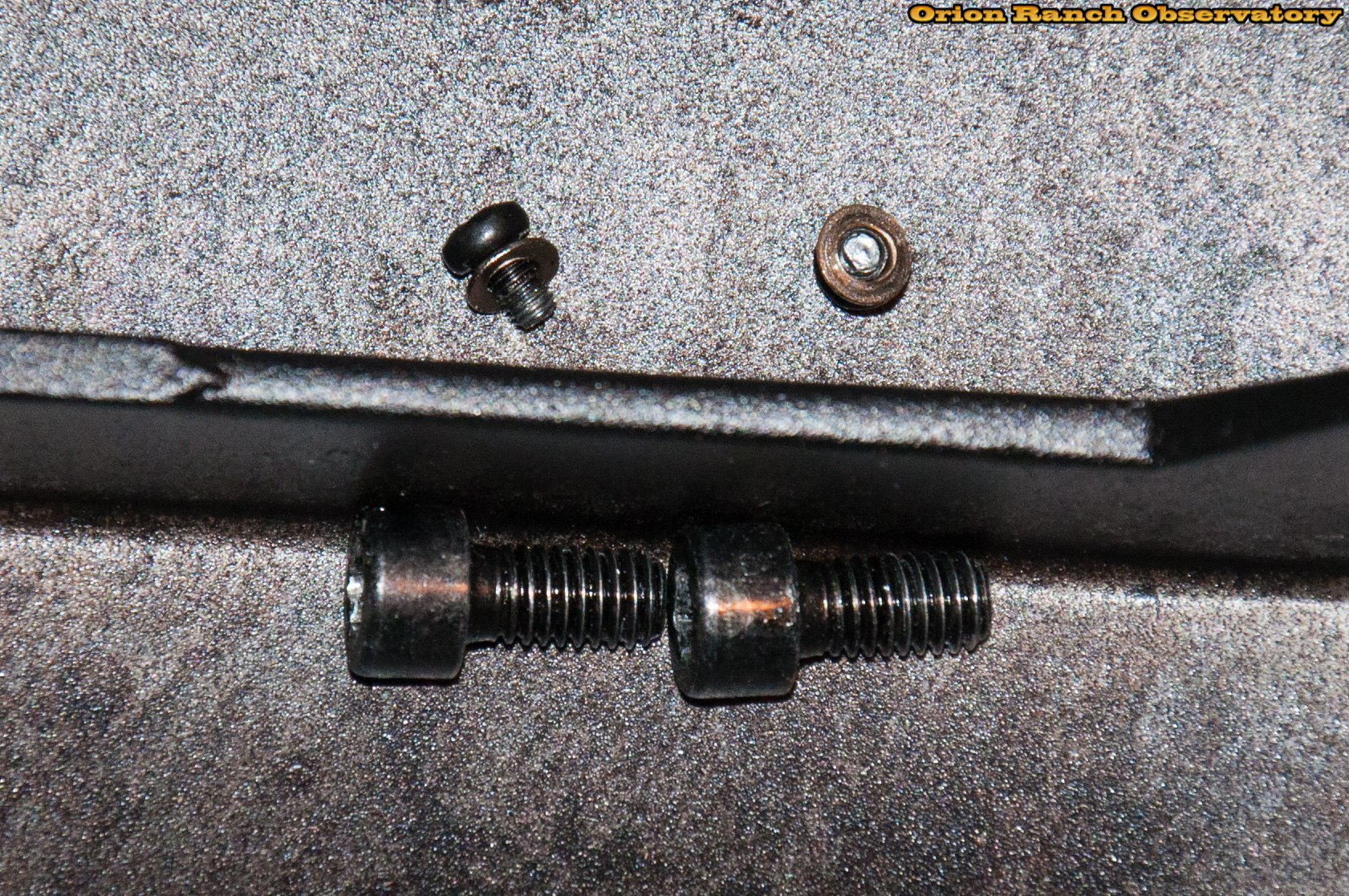
Now comes the fun part, working on the drive assembly itself. I start by loosening the gearbox. Two screws hold the gearbox to its mounting bracket. Removing them allows it to rotate around the worm gear axis.
Here it is tilted up to expose the two socket head cap screws that hold the whole assembly to the frame.
Removing the two socket head cap screws releases the drive assembly.
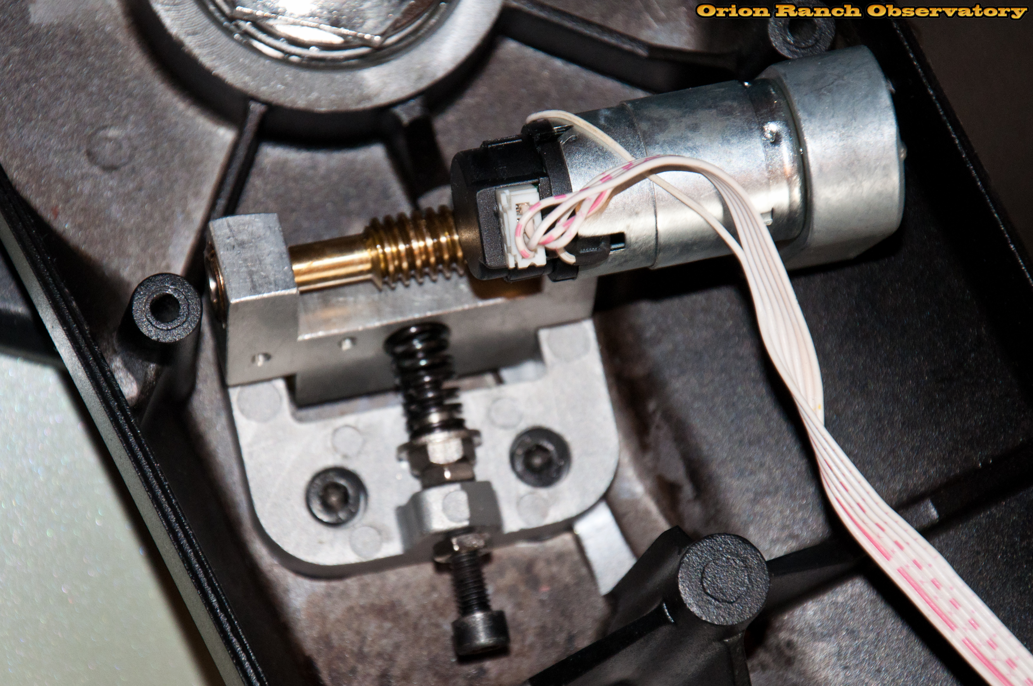
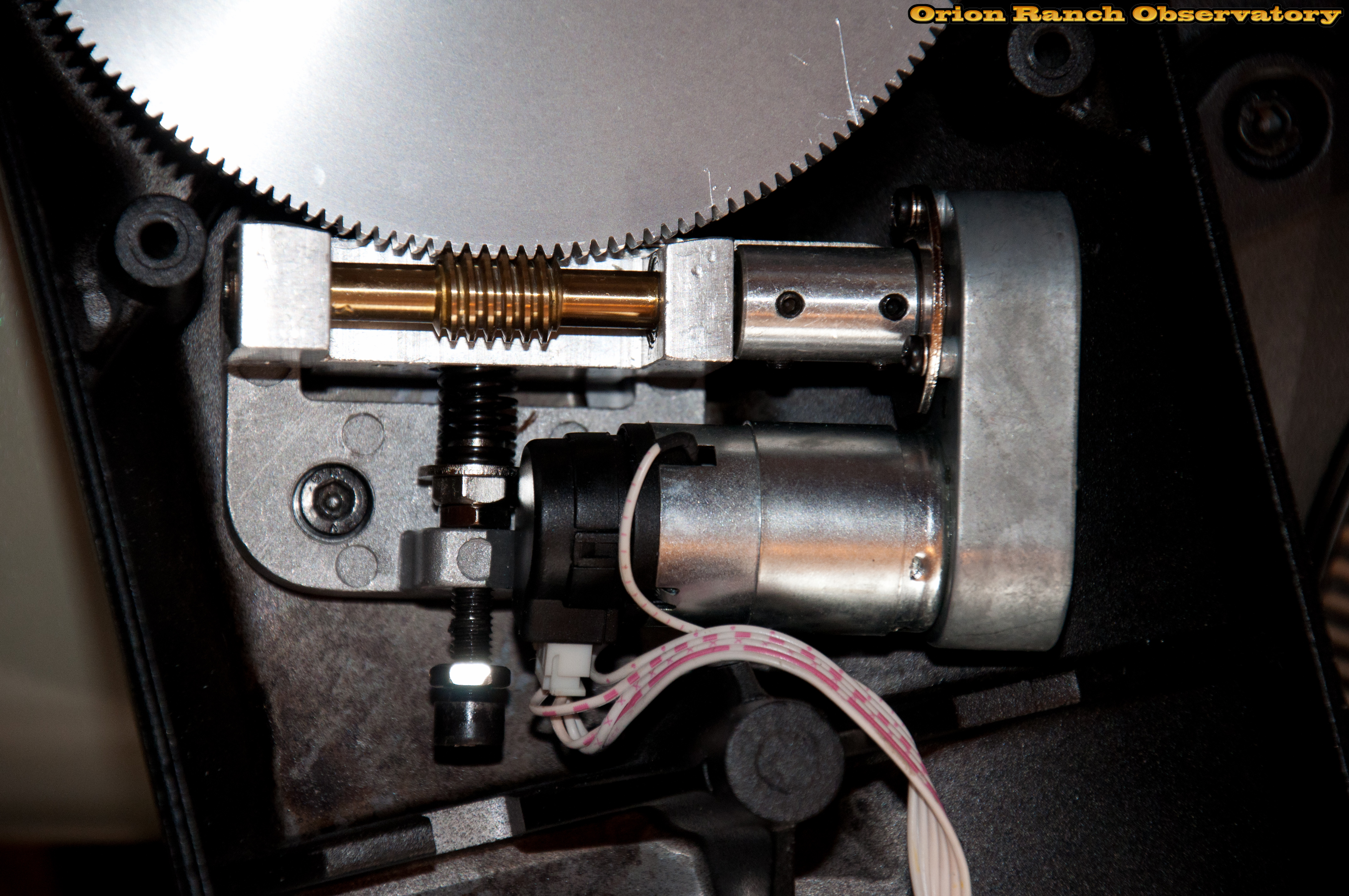
With the drive detached, we can inspect it from the sides. The “left” side of the drive shows the pivot set screw, worm bearing, encoder, and tension adjustment screw.
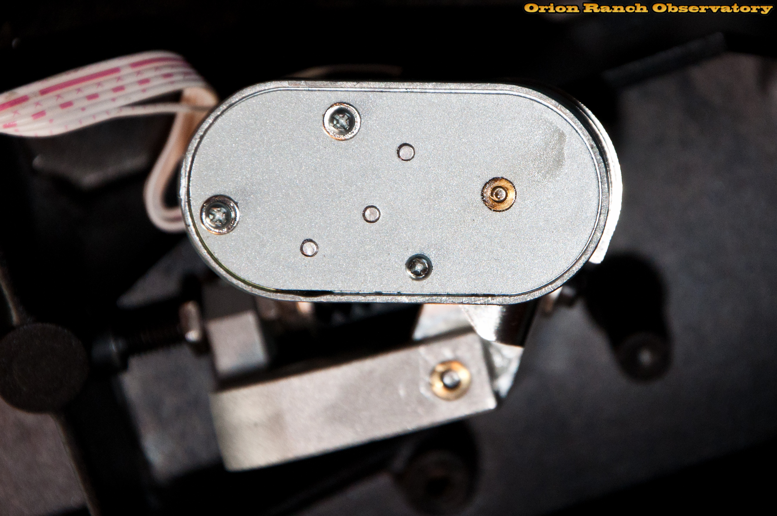
From the other side, the cover of the gearbox is held with three screws, and you can see the exposed pivot pin and bushing.
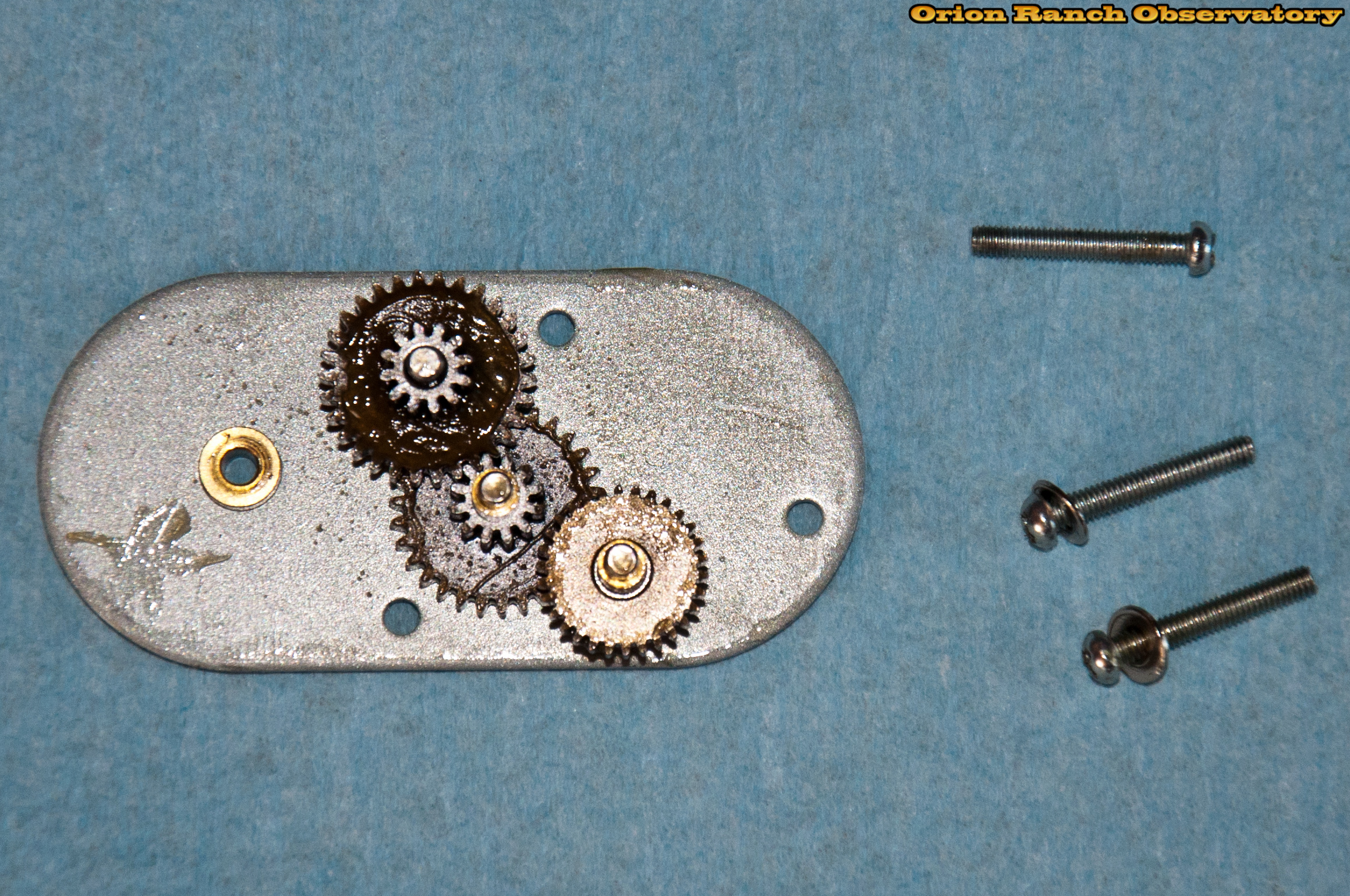
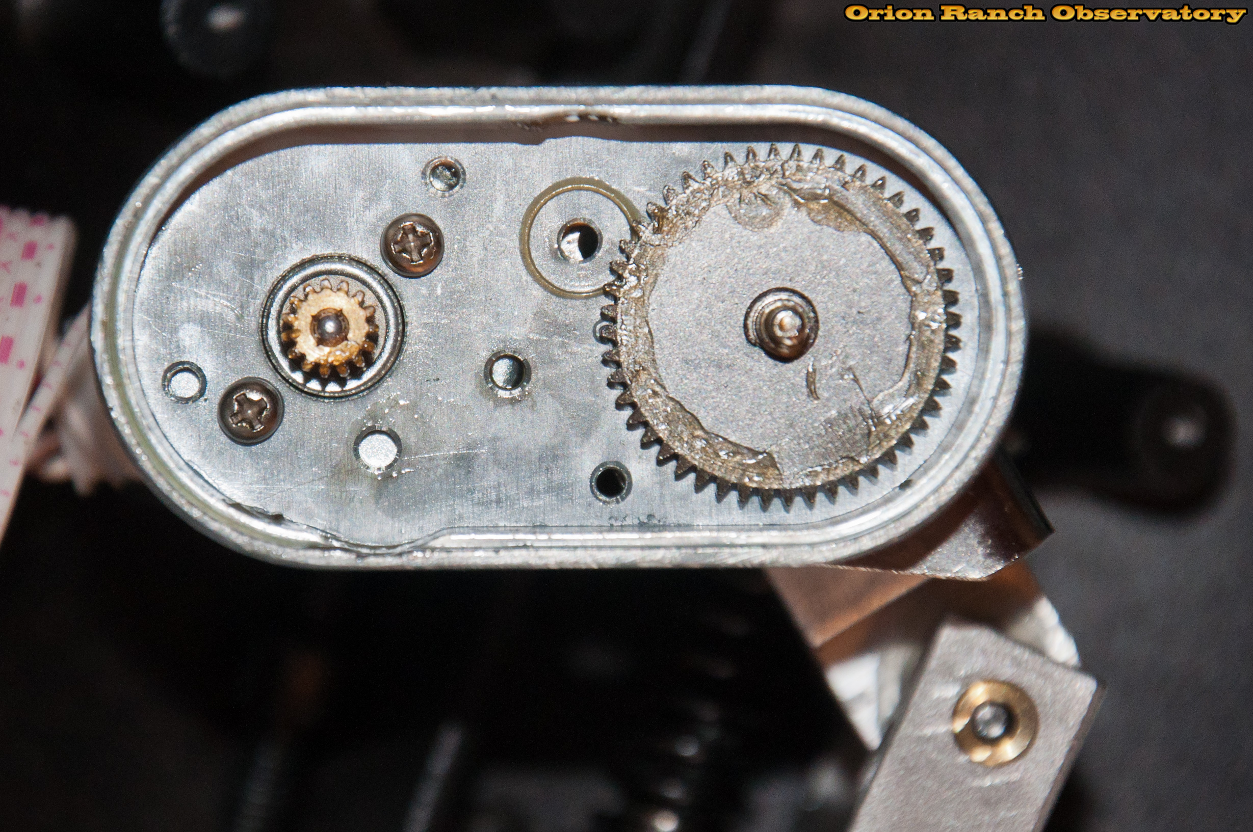
Removing the thee screws to expose the guts of the gearbox reveals five gears total. There are three floating gears and spacers on pins in the cover and then the motor and output shaft gears.
After removing the set screw and sliding out the pin, the assembly comes apart. The bushing inserts are both through-hole and nothing holds the pin in other than hydraulic pressure of the grease. That’s why when I got this scope the DEC axis bounced all over the place. The pin had slid out of the bushing on the set screw side and was allowing the worm to move back and forth about a centimeter or so.
The shaft coupling appears to be Loctited to the shafts and won’t come loose even with set screws removed.
After cleaning and oiling inaccessible bushings and re-greasing everything, the drive is re-assembled. Keeping the pin in is tricky when installing the set screw, since the grease and any air pressure wants to push the pin out. The set screw must be tightened enough to clamp the axis snugly enough to keep it from sliding back and forth on the axis pin.
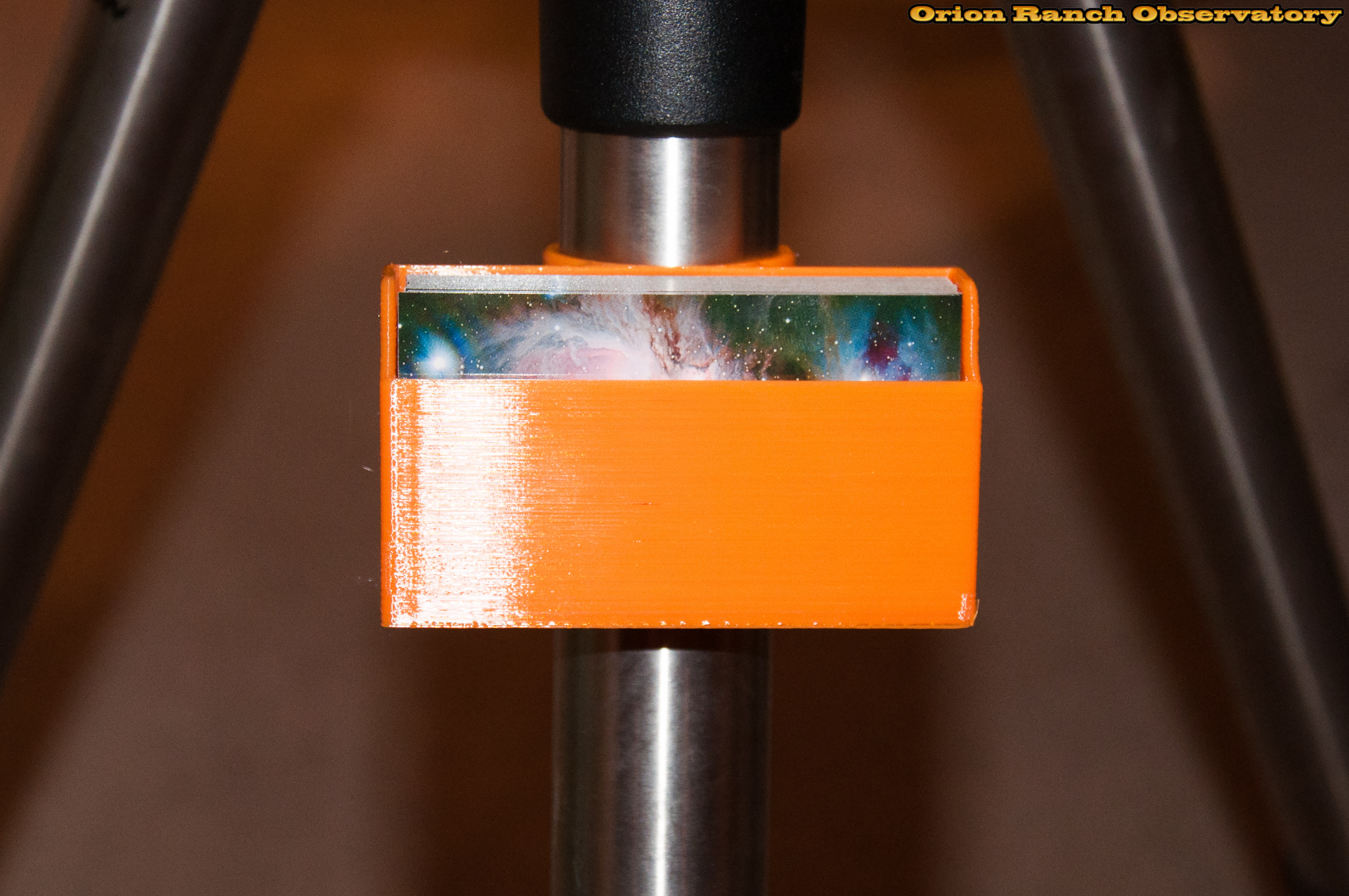
Now I can install and align the main drive gear and drive assembly prior to re-greasing.
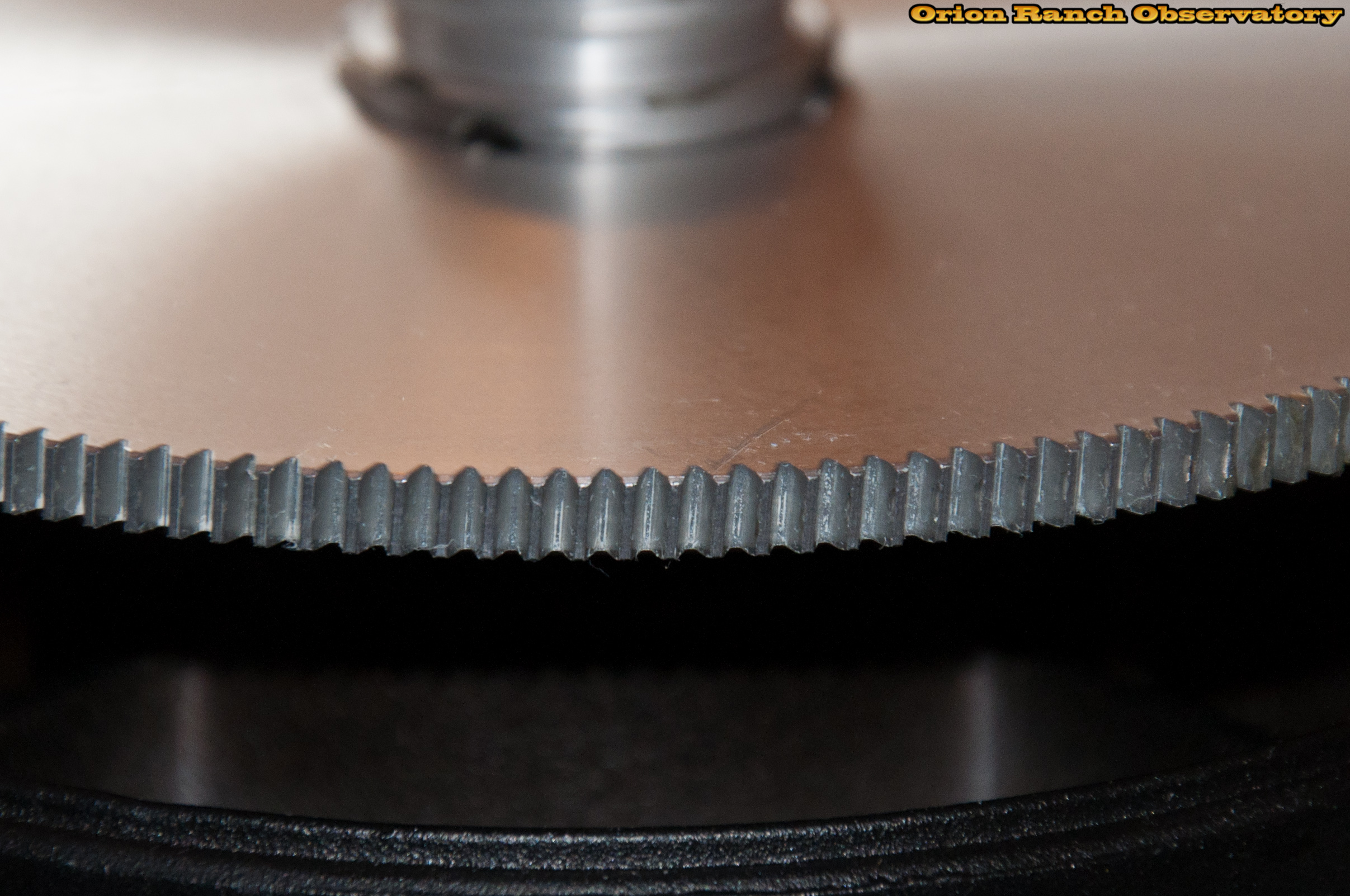
Here’s a side view of the worm gear teeth while they’re nice and clean. This is definitely a much lower-end gear compared to the azimuth axis gear. While it’s obviously not as critical as the RA axis, it’s still more cheaply made, with just a straight cut at an angle, instead of the curved cut on the brass RA axis gear.
Between this and the difference in the drive gearbox, it’s apparent why my RA gearbox has the 1:1 spur gear with no cover, instead of the similar gearbox as the DEC axis as shown in Gary’s guide. If you go back and look at that guide, you’ll see that the older CPC used the same aluminum worm gear and five gear gearbox on both axes, while on the CPC Deluxe HD, the RA axis uses a bigger brass worm gear with a better overall tooth profile. That would change the gearing ratio to the servo motor to get the same overall encoder feedback.
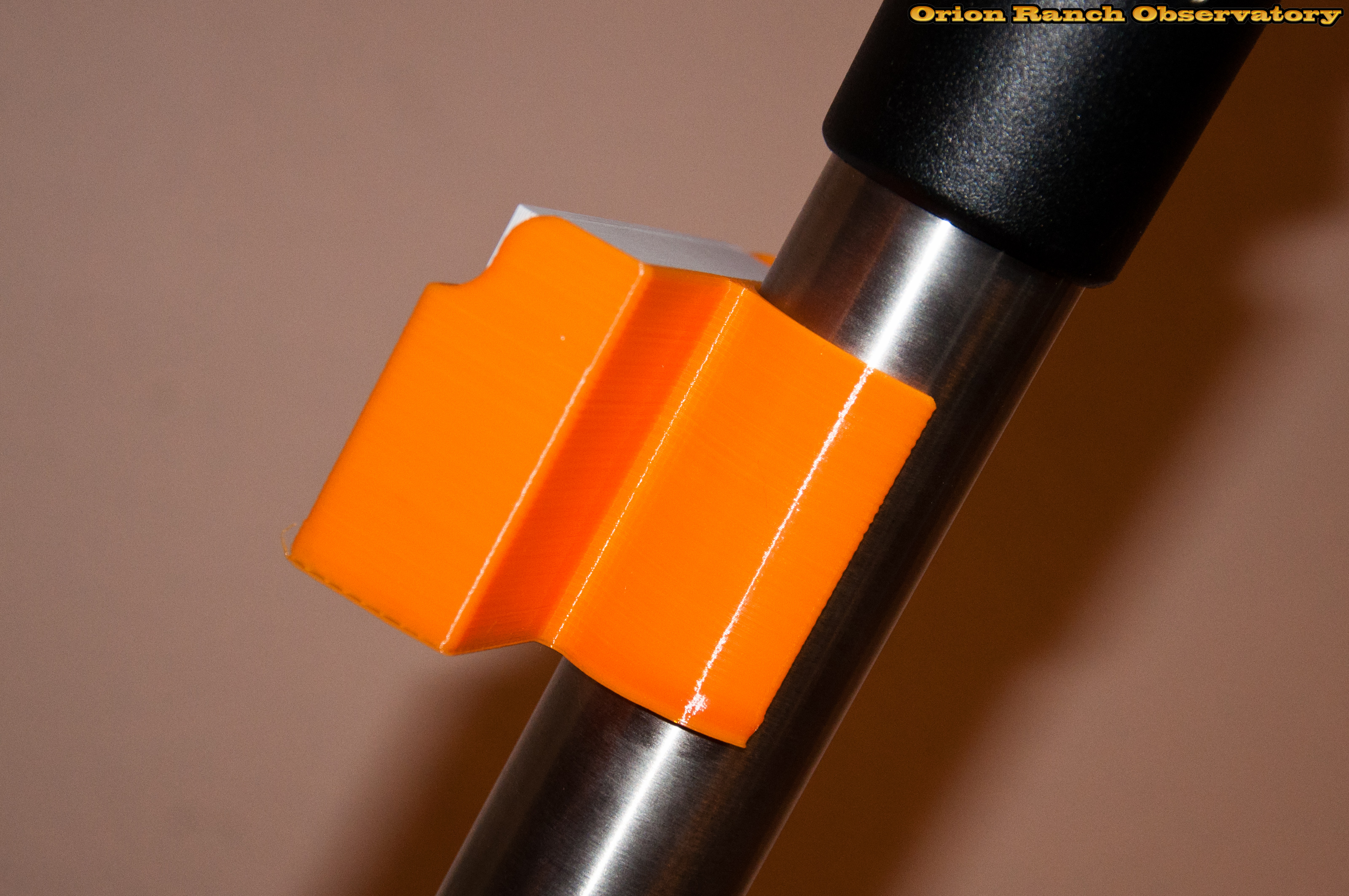
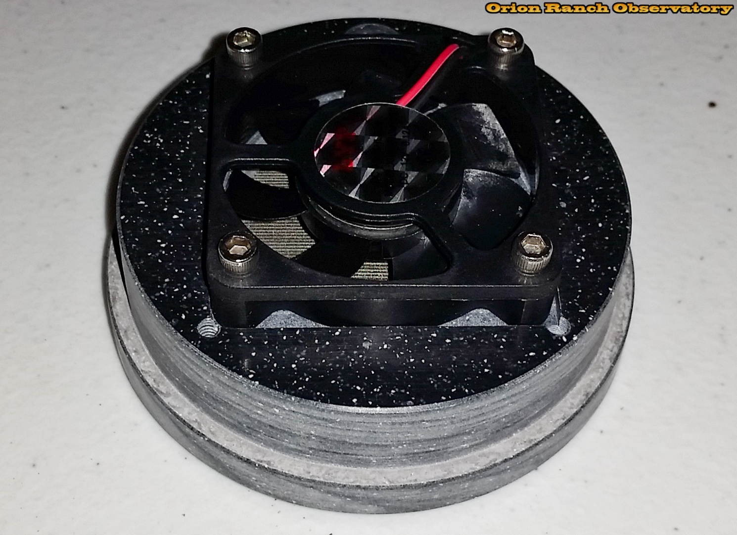
Here’re some views of the worm gear assembly re-greased and ready to go.
For a real hoot, check out this video of the drive in operation, after running it back and forth to run-in the grease. It’s amazing how much wobble the gearbox has on the coupler, which is why it’s mounted on a spring bracket.

While re-assembling the cover, take note. The upper two screws are of different length, with the longer one for the thicker side of the fork pylon. The two screws should extend through the same length.
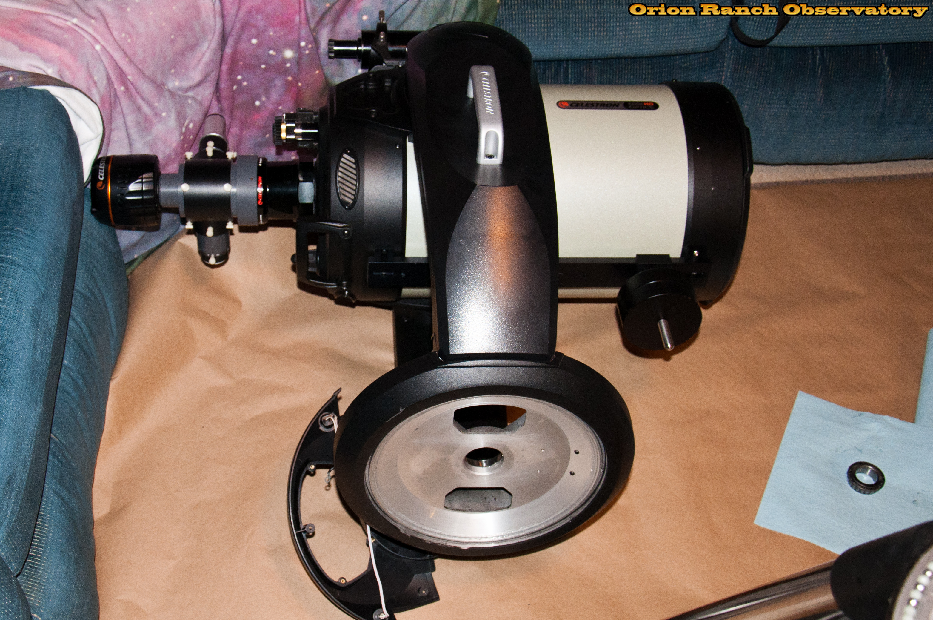
Now on to the handle-side axis. Remove the aluminum handle first with the two large set screws that attach it to the aluminum frame. The remaining six screws that hold the plastic cover are the same as the other side.
Here’s the handle side cover, inside and out.
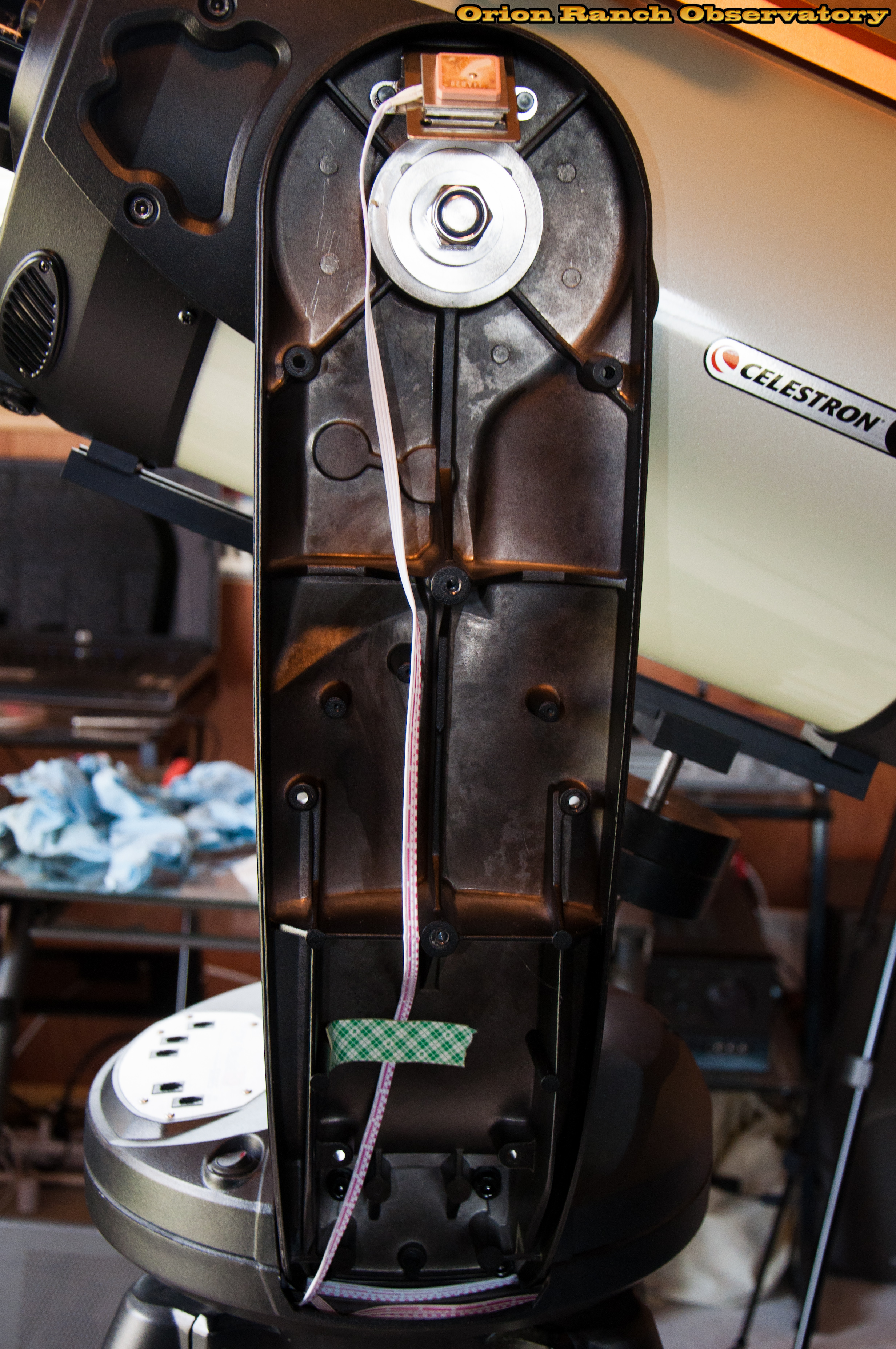
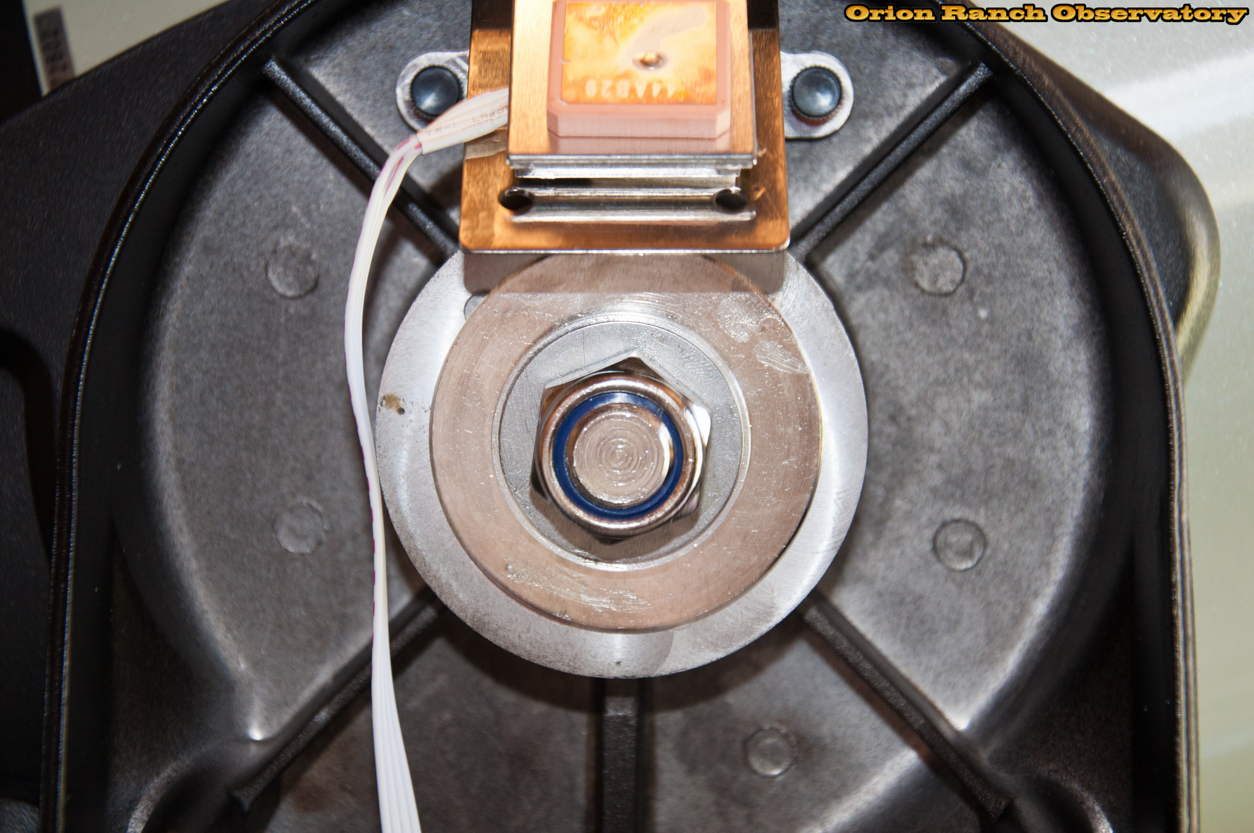
And the interior of the handle side fork pylon showing the simple lock nut and the GPS antenna. The antenna is well placed for Alt/Az mode, but not necessarily ideal for wedge mounting.
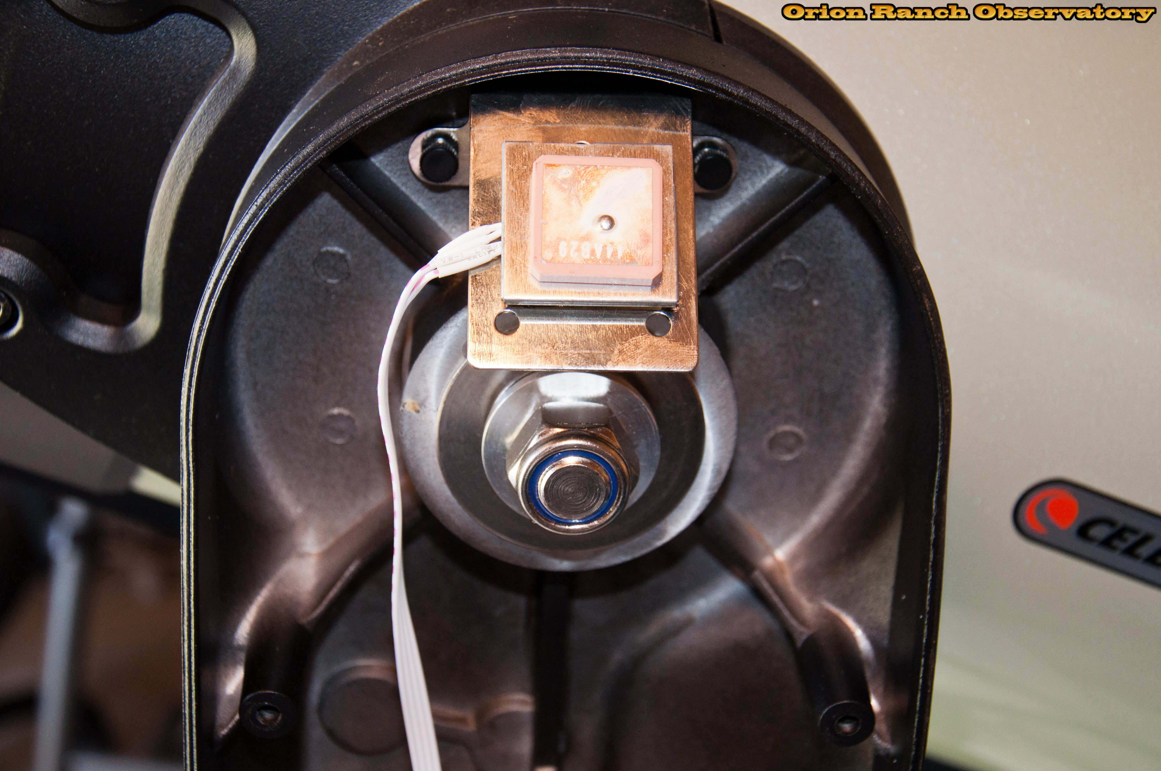
Here’s a closer view.
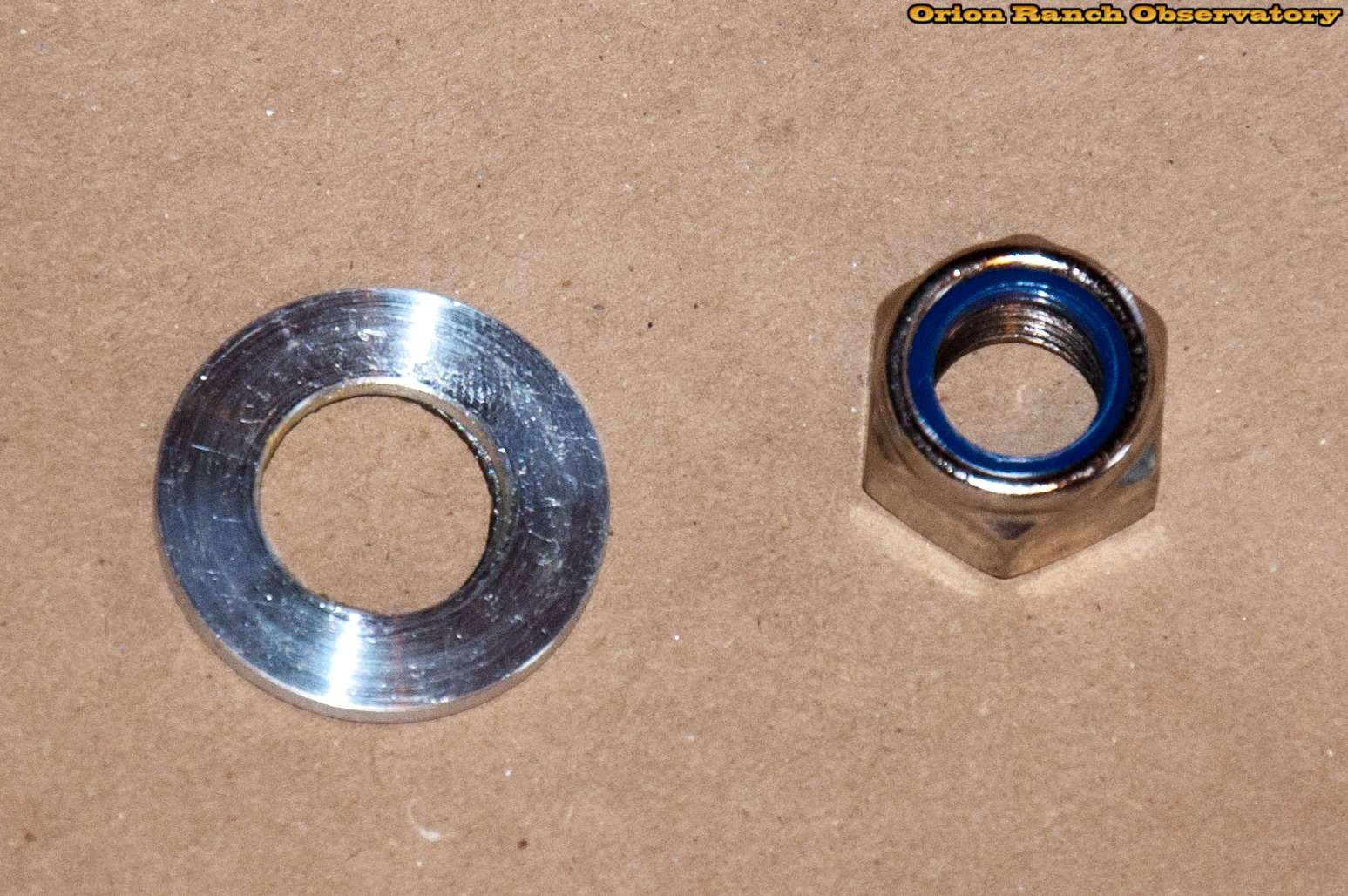
After removing the lock nut and washer.
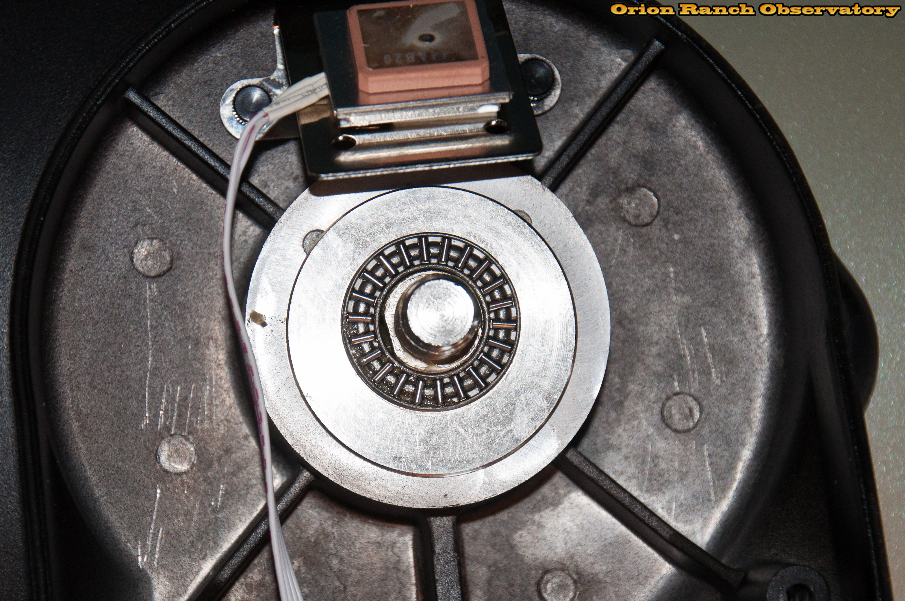
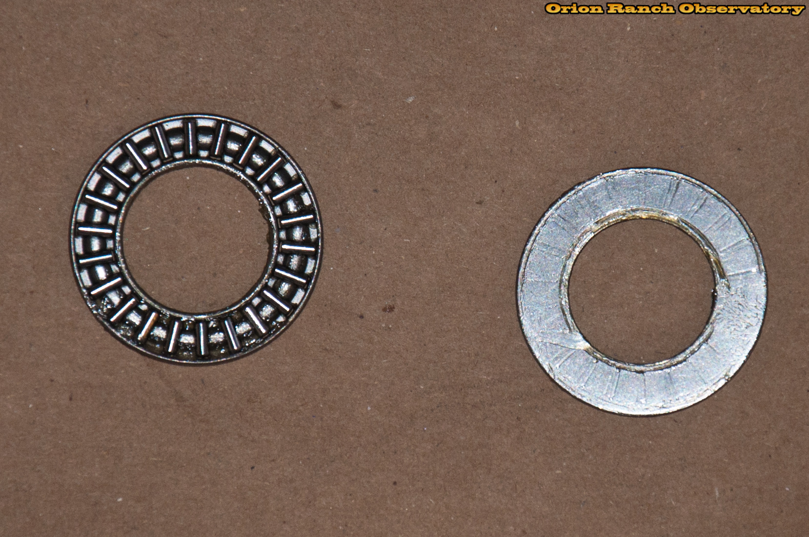
There’s a simple flat roller bearing with another steel washer under the lock nut and several washers.
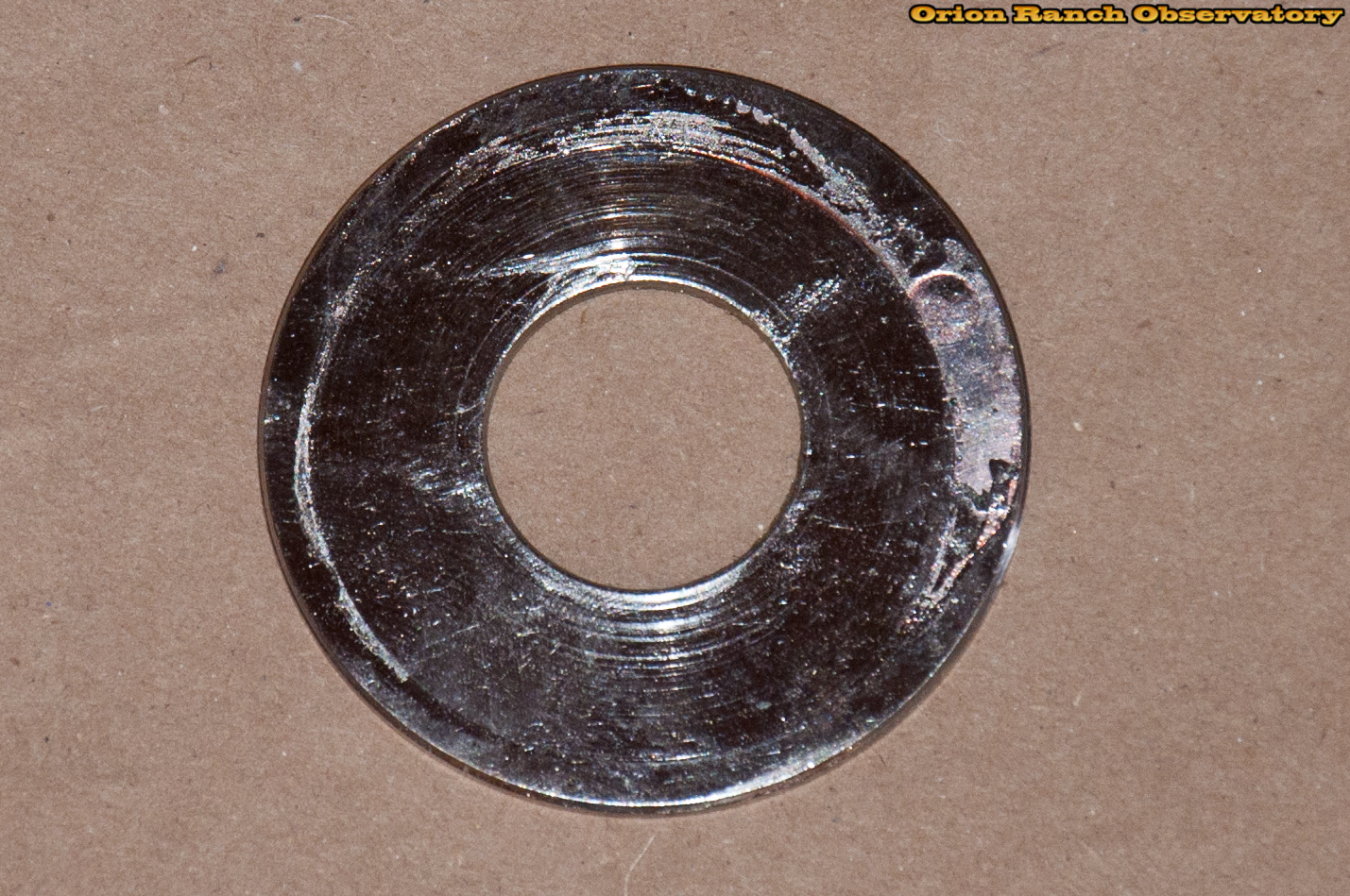
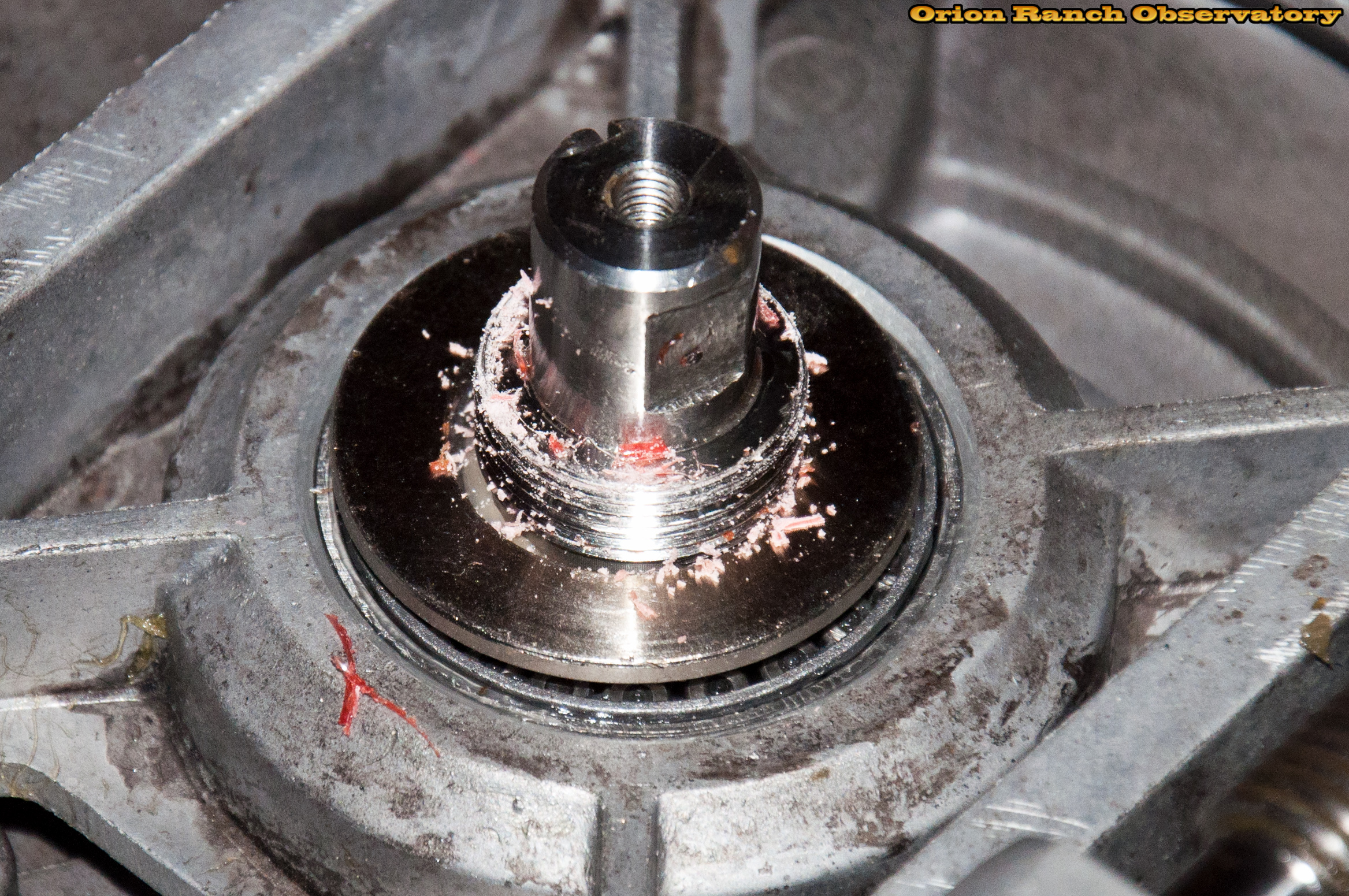
The roller bearing rides on a large flat washer held on with a thin layer of red Loctite. Mine was not properly centered (obviously slipped before the Loctite hardened) and was rubbing against the top of the shaft.
You can see the Loctite residue on the back side of the large roller bearing washer.
The thrust bearing is under a special lock ring behind the washer. This is where I stopped due to the special tool required for removal. I figure the grease is probably still fine and if I have to get back in it later, I’ll deal with it then!
Here’s what it looks like after centering the larger washer and re-installing the re-greased roller bearing and lock nut.
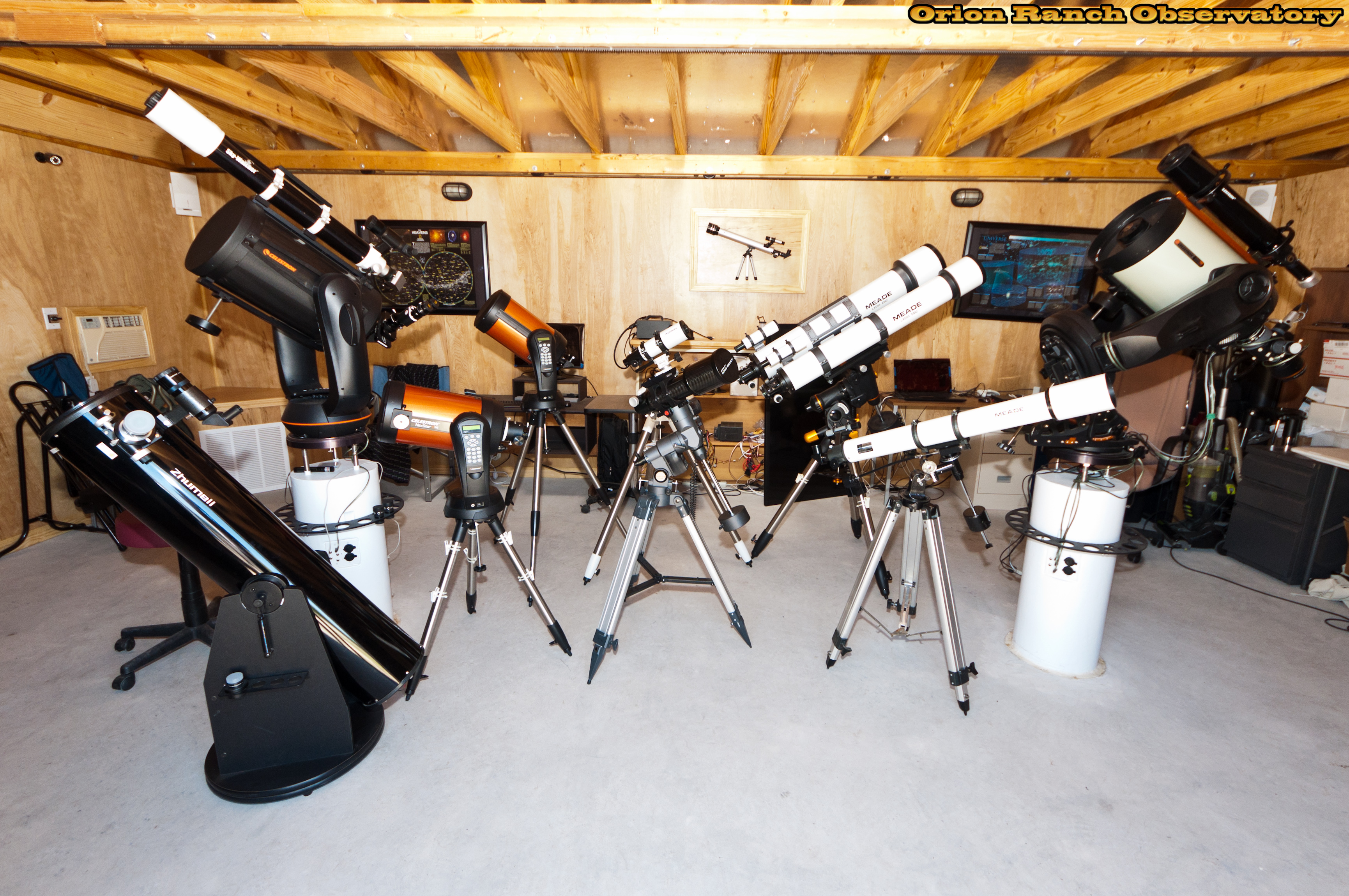
And finally, putting everything back together in reverse of the way it came apart, the scope is mounted back to the pier.
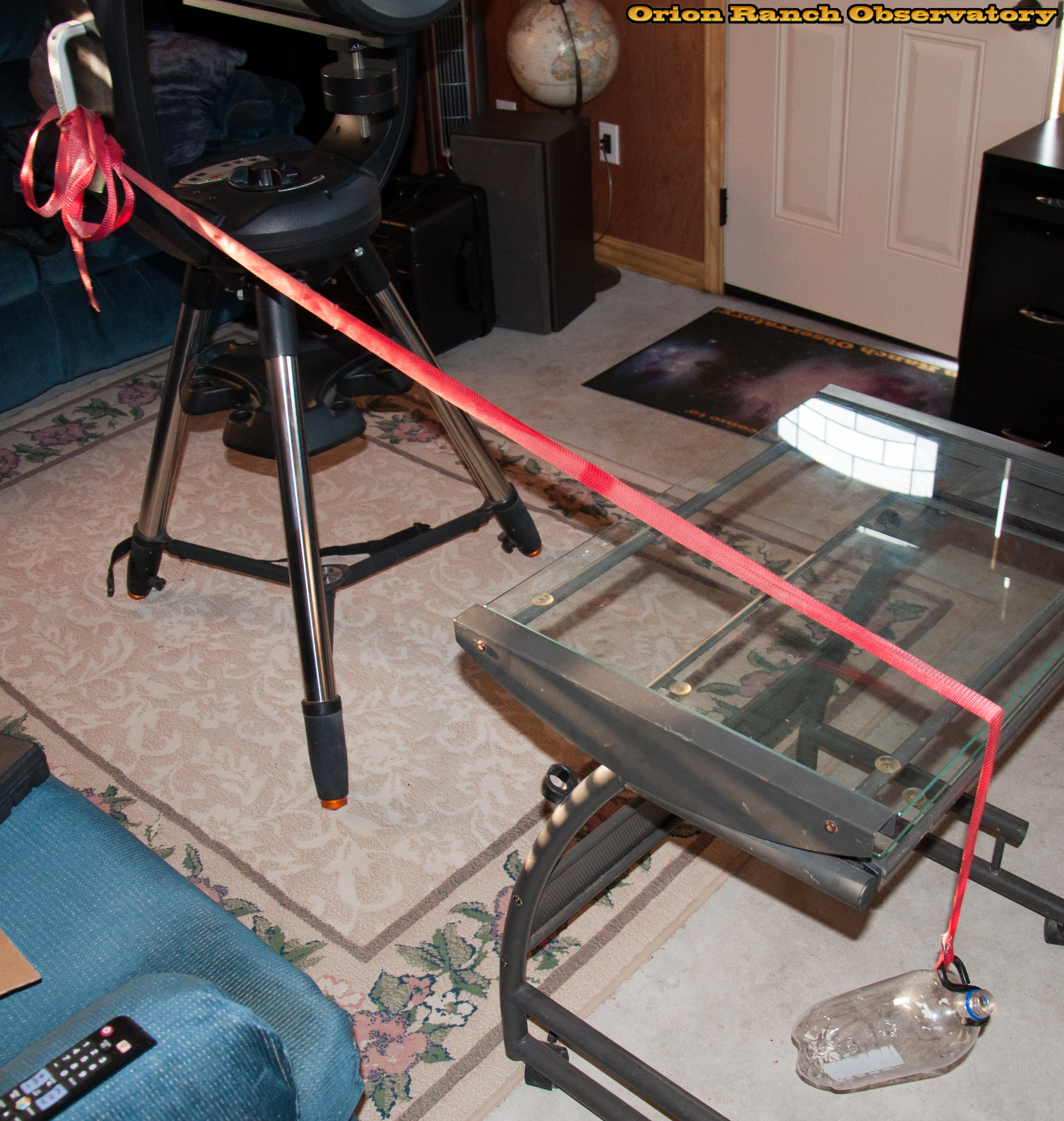
It’ll be a while before I have time to test everything well and come to any conclusions on the performance of the upgrade/repair/destruction I accomplished here! However, a few comments so far. First, while I was a bit worried that the azimuth bearing felt a bit gravelly when I swung it around manually in AZ mode, once I put it on the wedge, things changed drastically. The ride is extremely smooth under all that offset weight, which puts much more force than the vertical force in AZ mode. I do hear a small clatter every 360 degrees when I roll it around continuously, which almost makes me wonder if I dropped a ball in there. I think it’s just one ball rolling over the small gap in the balls in the outer bearing, but who knows. I can’t imagine how something loose would only clatter in a very narrow region. Beyond that, I do currently have a problem with the DEC axis slipping teeth when I try to pass a certain point. The setup is well balanced horizontally around the pivot, but not top to bottom, as you can see. Previously I had over-tightened the spring tensioner on the DEC axis so it couldn’t slip, but I think I’m going to try putting a piggyback on top again to better balance it and see if that works. I’d rather have the safety of being able to slip a tooth if something binds, but before I was getting quite a bit of hysteresis/backlash from the gear not meshing tightly, so we’ll see if I have to dig back in and adjust that later.
One other thing I’ve noticed is that I may have done too good of a job of cleaning the rubber pads on the clutch plate and the gear pressure plates. They tend to stick when released and take a bit to break loose when released.
I did run some initial tests with PHD, and while I can’t say much about the RA performance, I did see a very regular sawtooth pattern on the DEC axis performance. That may be that my polar alignment is off, since I haven’t re-tuned the wedge after remounting, and it does have some play. From my initial alignment, the NexStar polar alignment indicates I’m off one degree in both axes. Interestingly, however, after having it lose communication on me and re-aligning, it indicated I was almost dead-on with only seconds of error, so who knows?!! This was also not a true 1:1 comparison against earlier results as I made one change to the PHD settings, going from the 0.15 pixel default to a 0.5 pixel setting for the minimum error setting.