Updating my All Sky Camera

My all sky camera had been out of operation for a year or more due to a flakey USB interface.  I’m not sure how much of that was related to my observatory PC as other USB devices give me problems there too, but basically I’d just get a handful of pictures before the camera would go offline.  There haven’t been any advances in USB over Ethernet (at least not in an affordable price range), thus, I decided to upgrade my unit with an embedded stick PC.  I bought a this new stick PC from Amazon (couldn’t find my old one, but it was failing on me anyway), but it was too big to fit in my old housing. 

Thus I altered the design to make the shell the outside diameter of the dome, but flared it down to the original diameter at the base so I didn’t have to redesign everything else.  It worked, but wasn’t terribly easy to get the thing assembled.  I also replaced the dome as it was pretty badly fogged.  Unfortunately I couldn’t get quite enough current to it through the 12V camera lead I had there for power, and POE couldn’t quite handle it either, so I ended up having to add a DC-DC converter to take the 24V supply voltage and give regulated 12V at higher current.  That made things really tight, so I’ll be redesigning the whole thing to have a wider base and more fan.  I need to do it anyway as the base is starting to collapse.  The camera isn’t quite in focus, and there’s a spot that hopefully can be cleaned off as opposed to a burn spot on the sensor, but I’m not getting back into it until I’m ready to replace everything!  The PC also has some bright blue LEDs, but luckily it doesn’t appear to affect the imaging.


Posted in Uncategorized | Leave a comment

ORO Back Online!

Well, after about two years of being shut down and occupied with the construction of our new house, I’ve finally started taking some time to get back into astrophotography.  On Black Friday we started looking at solar scopes and H-Alpha filters and I ended up buying a used DayStar Gemini Quark. 

Using my QHY5III178 as a monochrome camera, I was able to capture a few videos and get them processed into some reasonably good images.

After that, I managed to repair my CGE Pro (see the video at https://youtu.be/UoY_97RK67w) and rebuilt my imaging rig using a mini PC that rides on the OTA.  This eliminates all the long control cables from the mount back to the laptop I traditional used.  It’s a bit tricky to run “headless” without a monitor or keyboard, and my traditional Chrome Remote Desktop doesn’t work reliably.  Luckily it has Windows Pro and thus I can use Windows Remote Desktop Connection, which works well over the local network. 

I haven’t had much integration time so far, but I’ve finished one short imaging session of M33. 

The observatory still needs a lot of clean-up, as does everything else around here, but I’m working on it!

Posted in Uncategorized | 2 Comments

Arduino GPS Replacement for NexStar GPS

Ok, after lots of research and experimentation, I’ve completed my Arduino Nano based GPS for replacing the NexStar GPS modules.  I’m going to give a detailed walk through of everything here so that it’s well documented, although it may take a few posts due to the picture limits per post.  I started from Barry’s repository on GitHub because he was doing the same mount and I didn’t need the display that others have added.  However, what I didn’t realize until I was part way through everything that the firmware there was incomplete and never actually worked.  Thus I had to merge some of Miro’s (ForestTree) fork back into my code to complete everything.  There are two main changes I made.  The first was to fix the serial interface so that it works as Celestron intends it to without any additional hardware (no diodes, etc.).  It also uses the busy control line like it’s supposed to.  The second was to add support for the GNSS NMEA sentences so that it responds to the $GNxxx sentences that the BN-220 generates when GLONASS satellites are visible, as well as the $GPxxx sentences from straight GPS.  I’ve created a fork from Miro’s version at https://github.com/L…ulf/nexstar_gps.  The way I uploaded it did a full replace on the .ino and isn’t giving a proper difference view, but I didn’t want to fool with figuring out how to fix it.  If someone wants to give me an easy way, I’ll see about doing so, but there are plenty of other difference viewers you can use.  


Barry’s wiring description wasn’t very clear on the wiring to the telescope, so I had to reverse engineer the NXW434 PIC microcontroller board that the Arduino is replacing.  

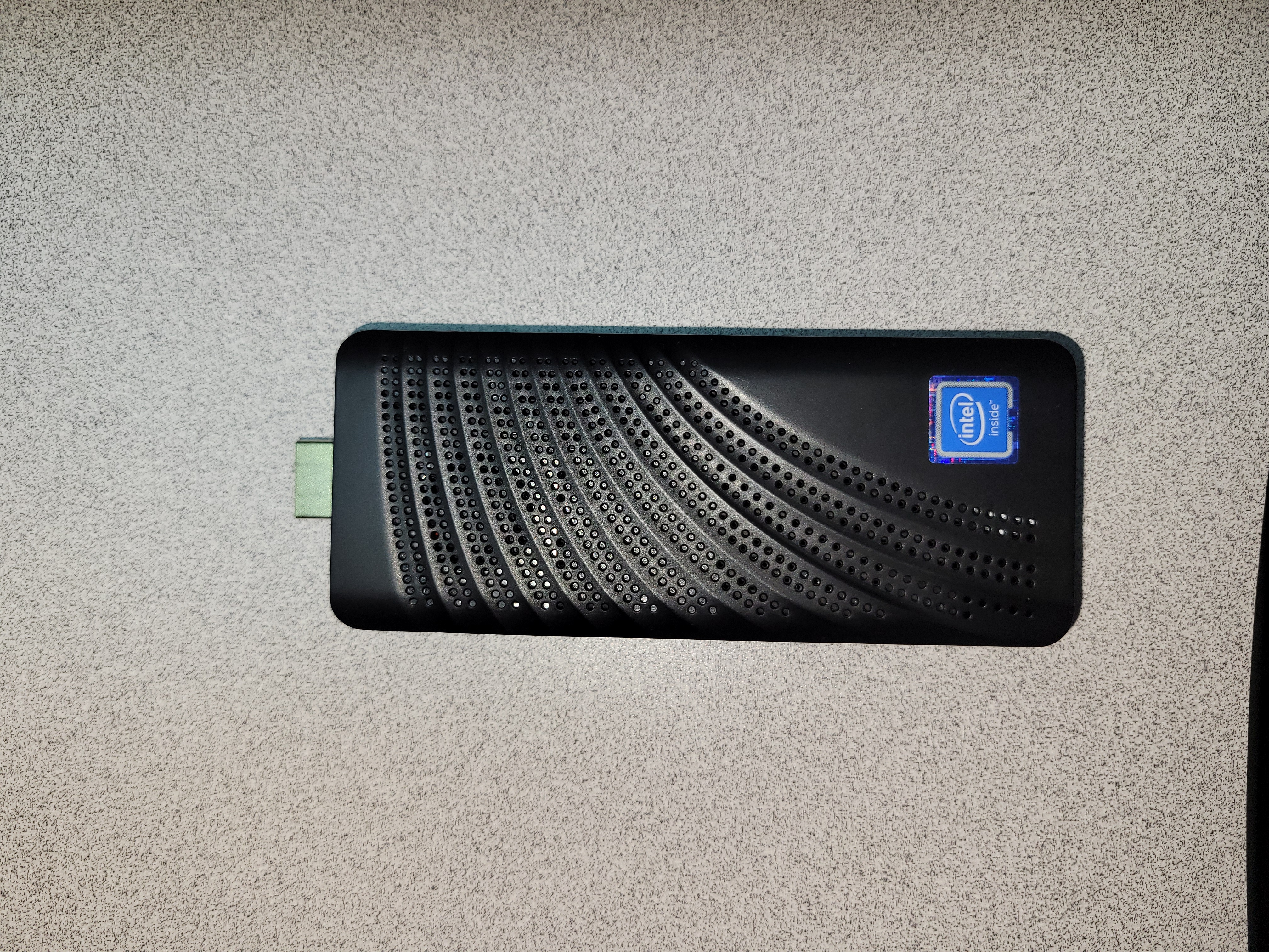
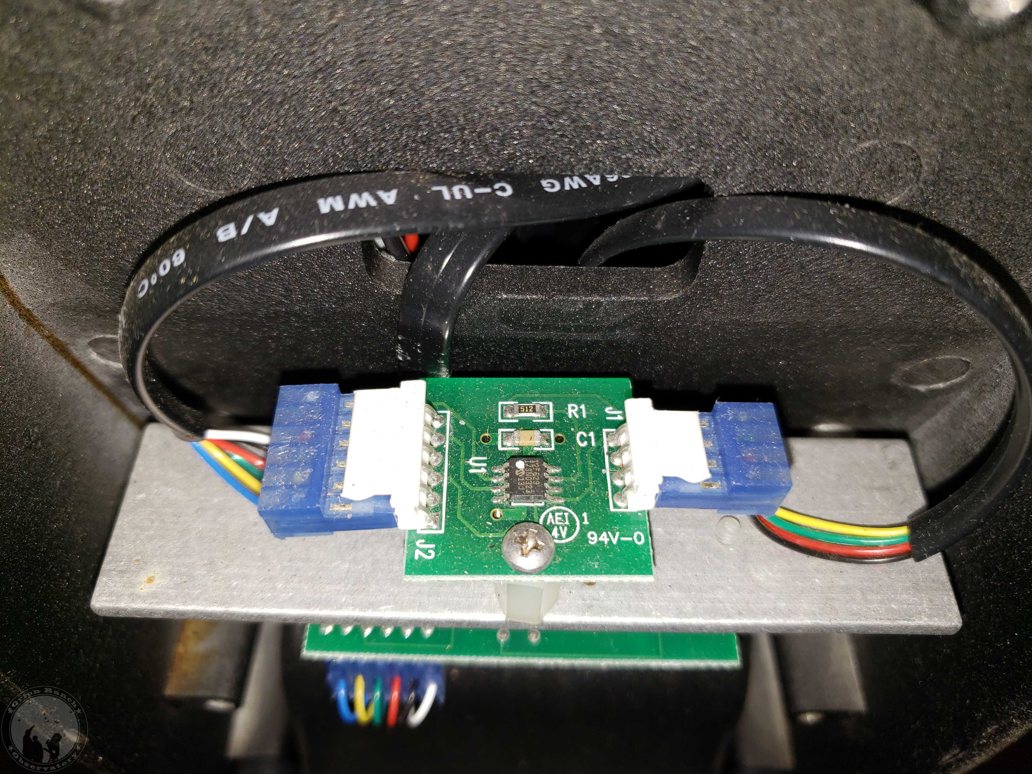
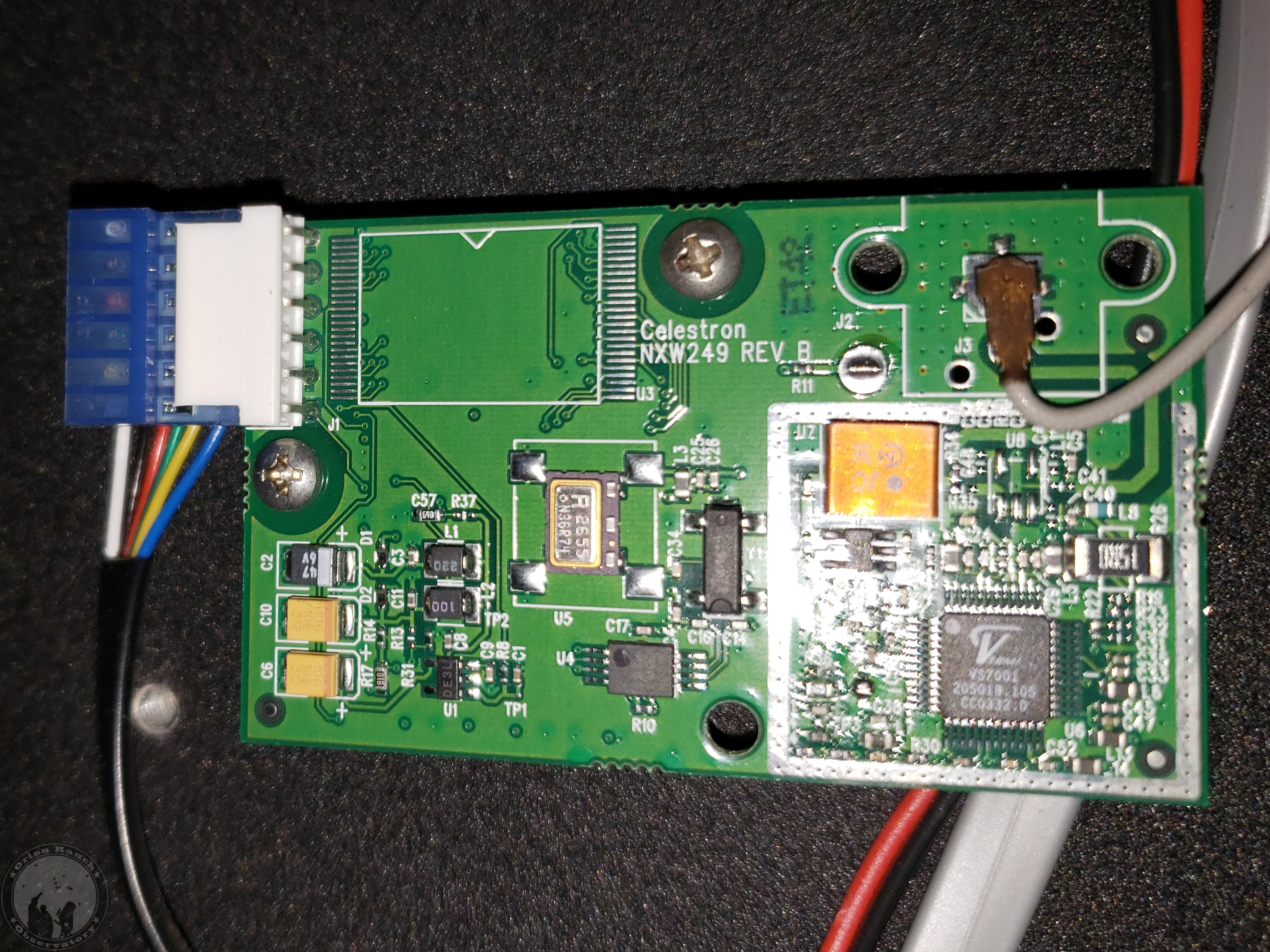
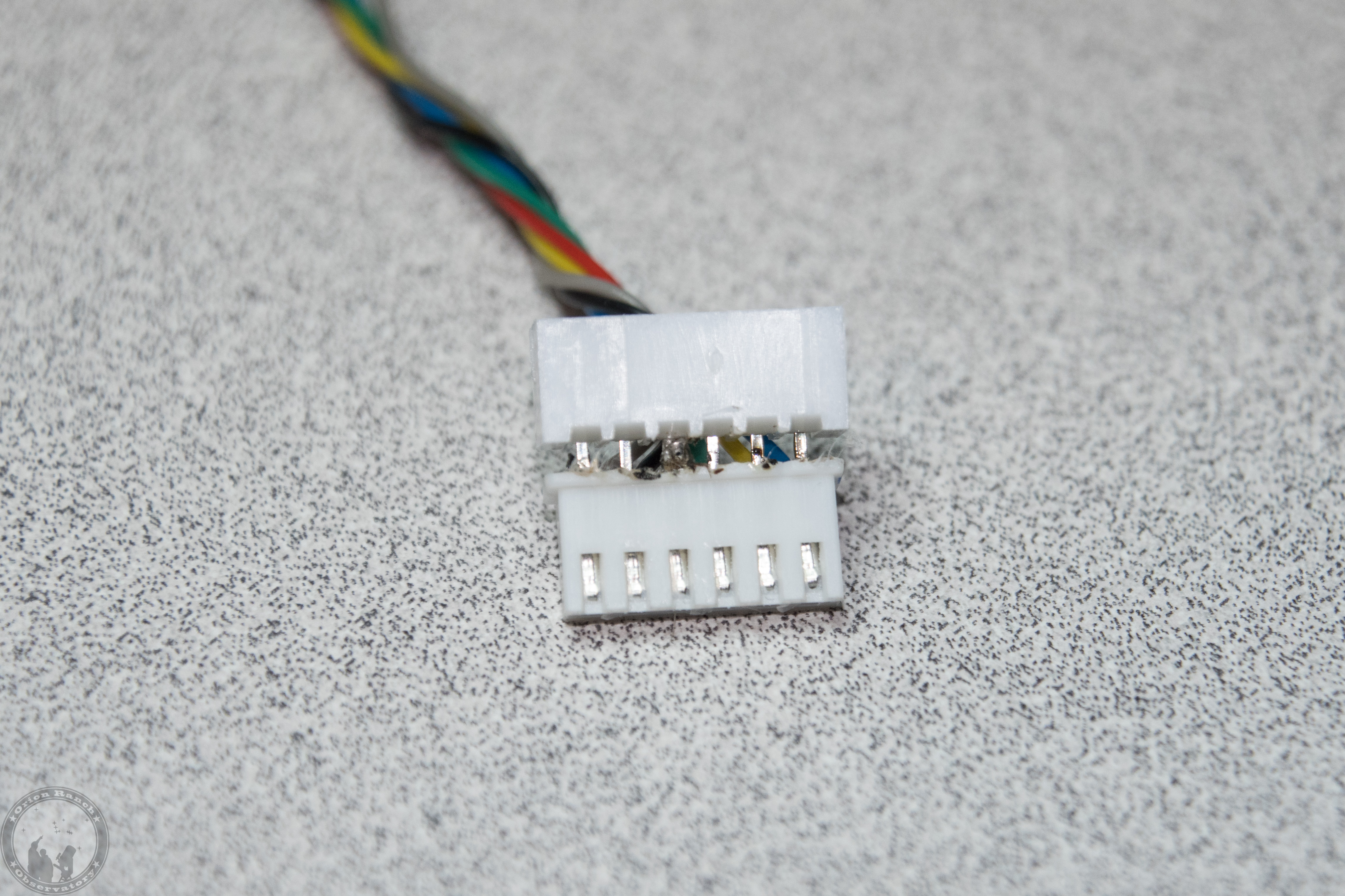
This connects to the NXW249 GPS bpard:

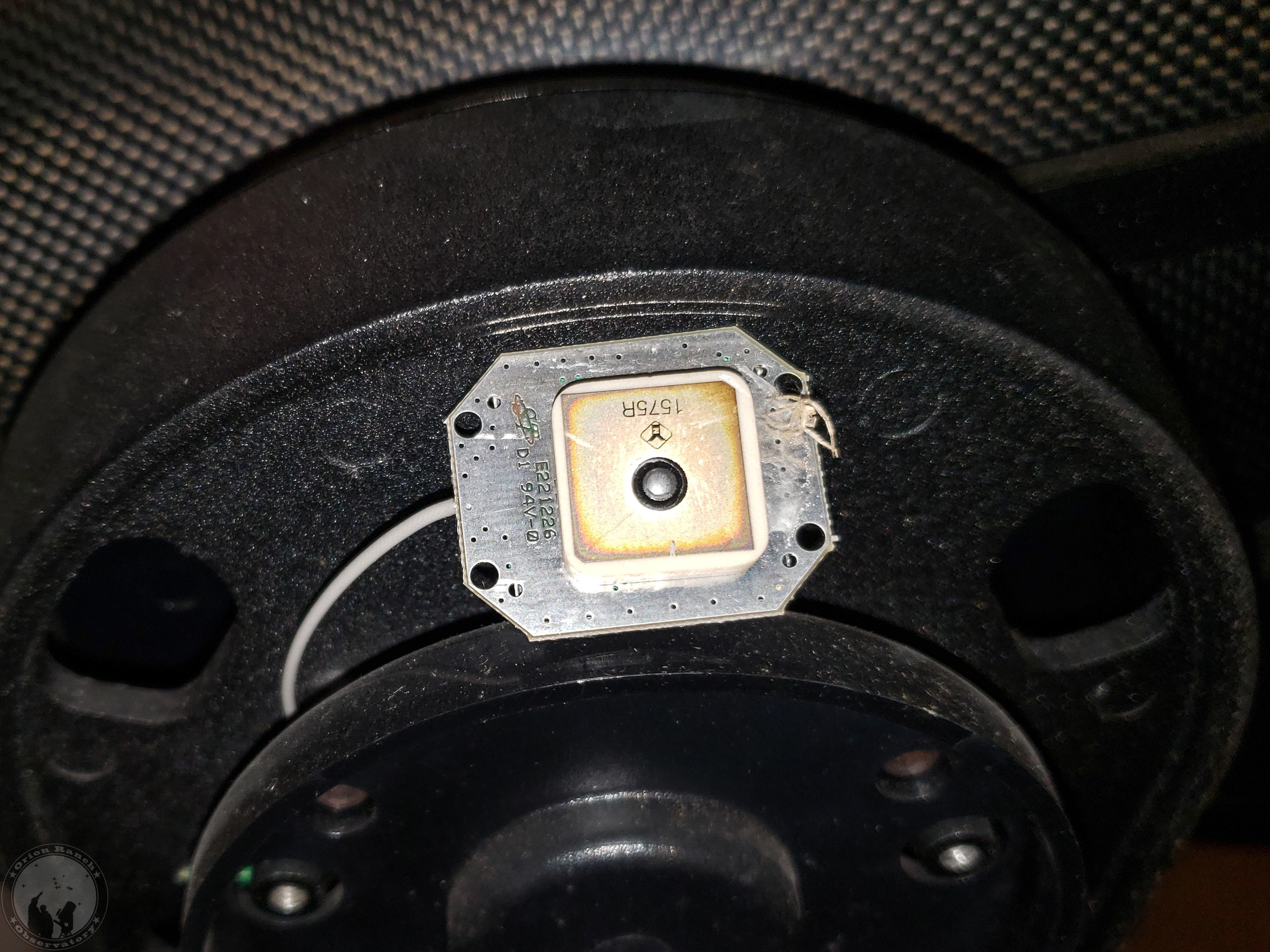
which coupled with the active GPS antenna makes up the parts being replaced by the BN-220.

I created a schematic for the NXW434 and posted it in my repository. 

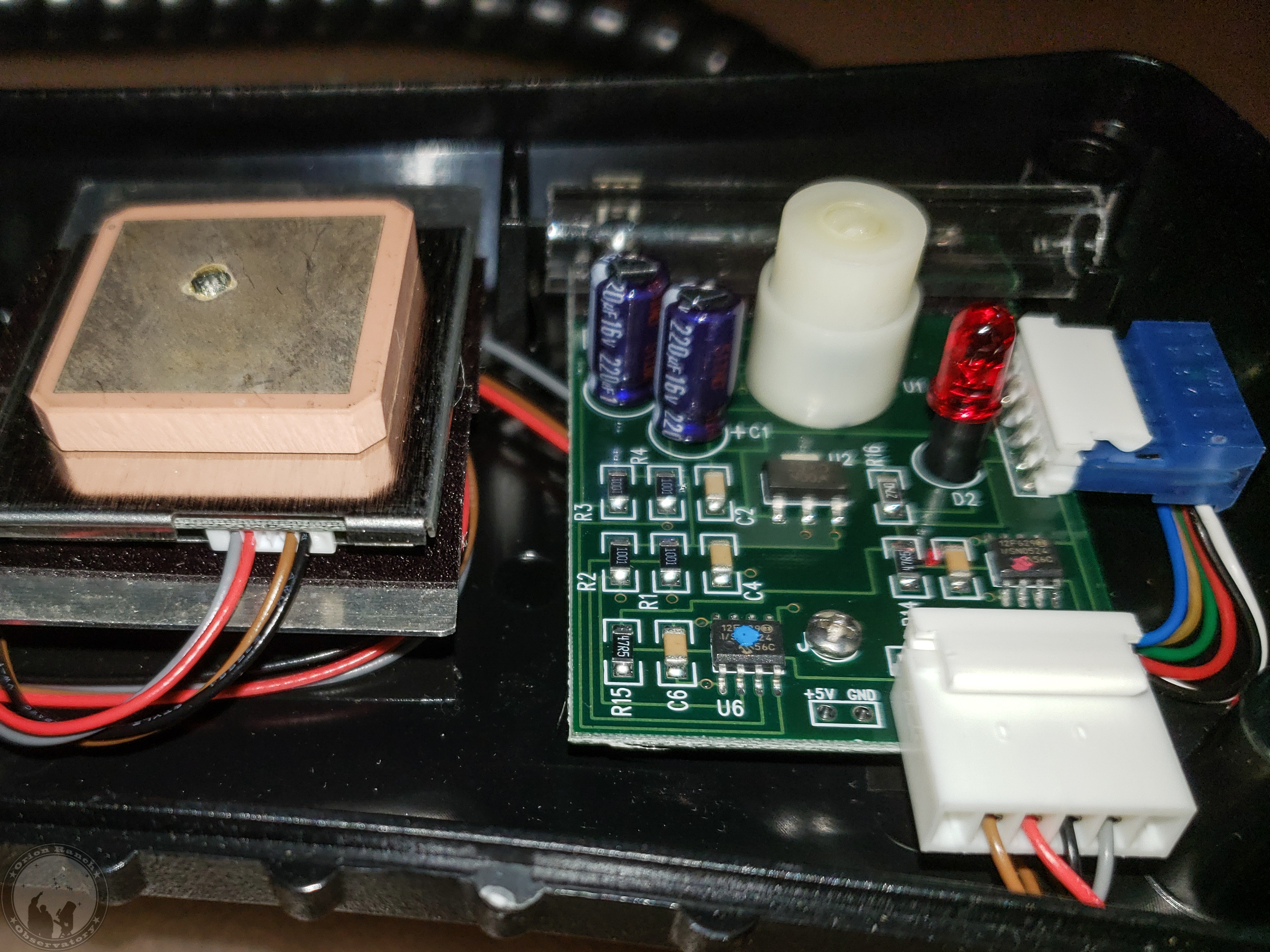
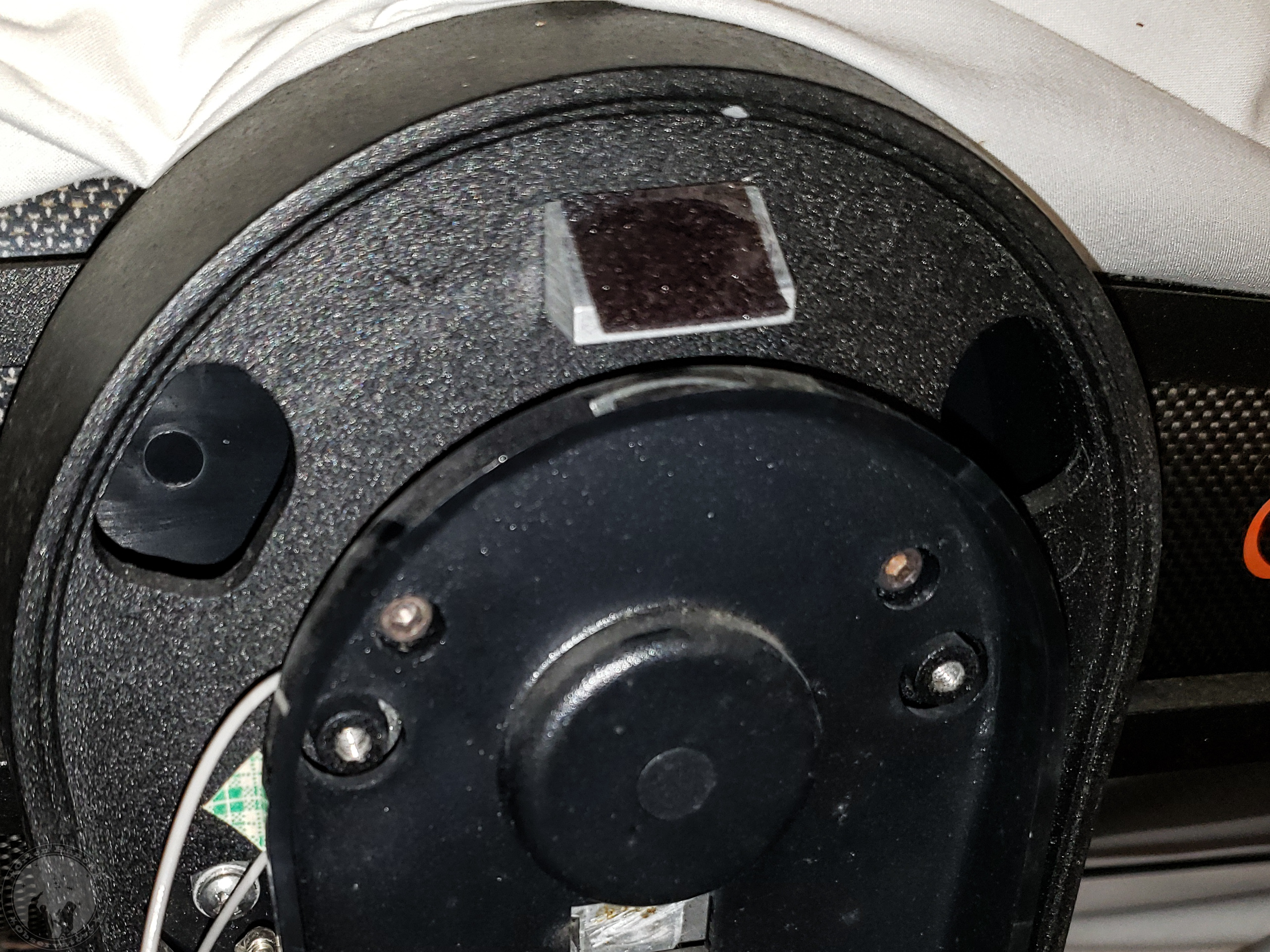
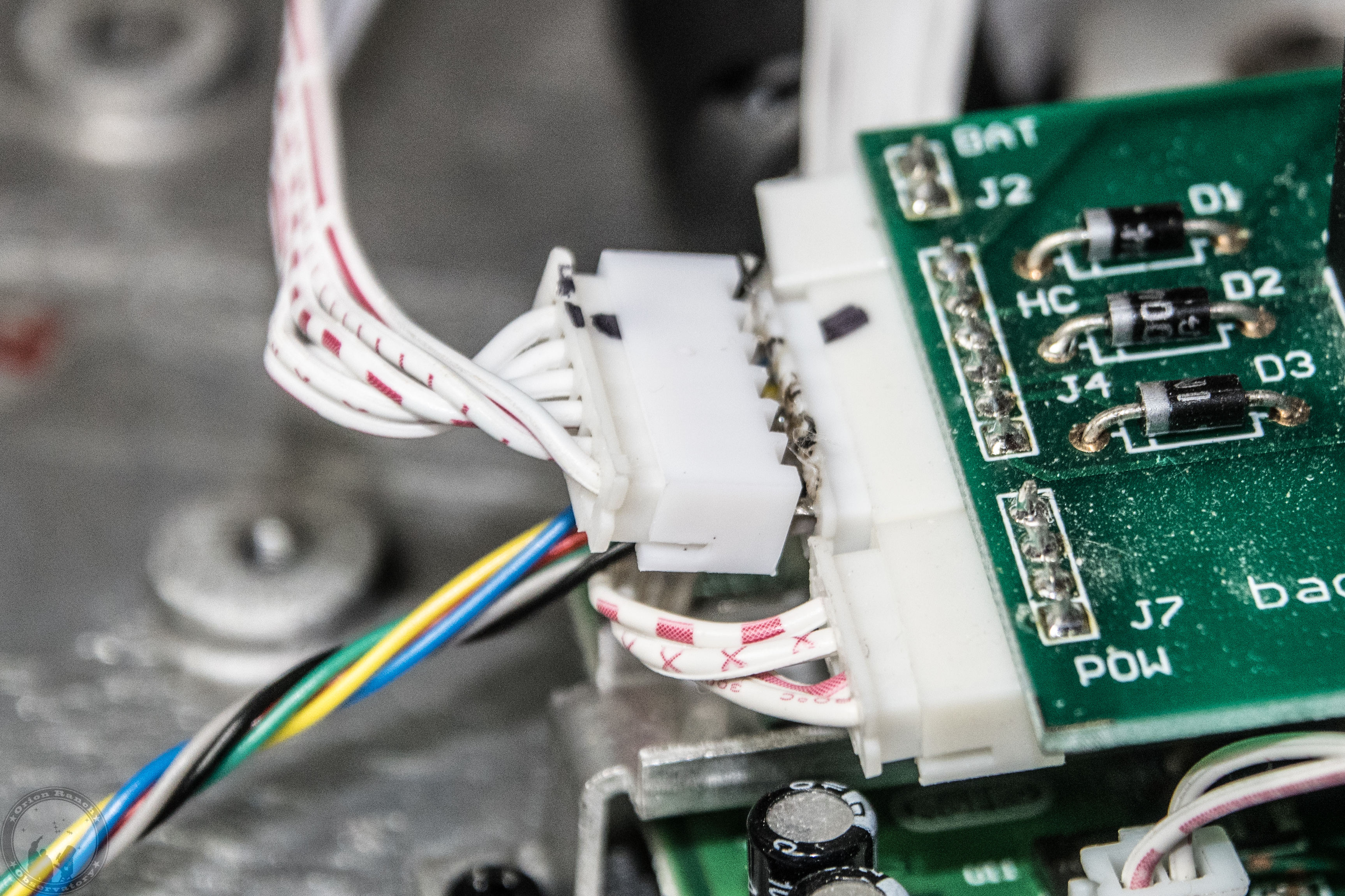
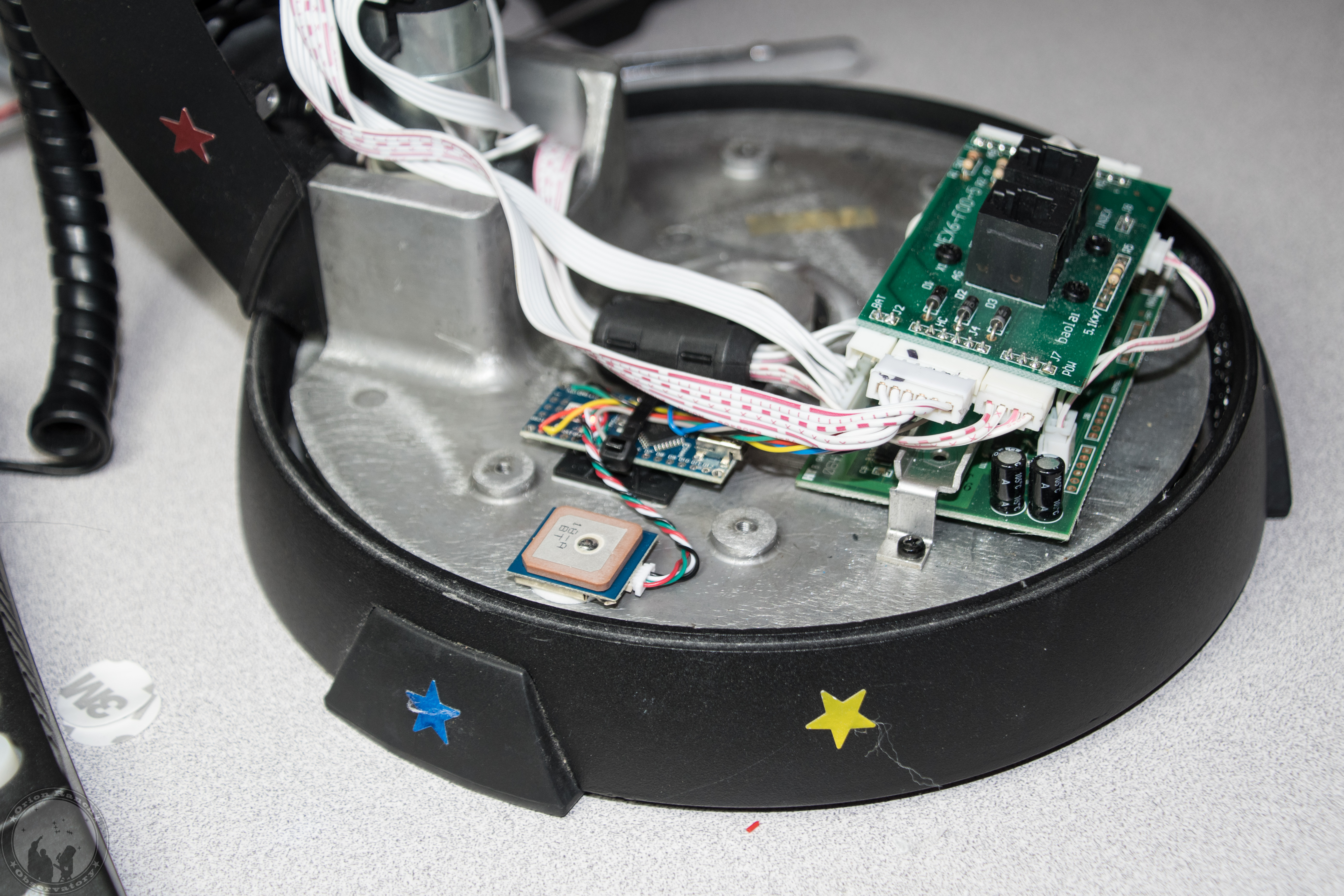
For reference, I also opened up my CN16 and found the exact same circuit combinations.  You can see the blue AUX serial connector on the right and the white GPS connector in front. The newer CPC style GPS module is under the antenna similar to the BN-220. Two Microchip 12F629 PICs identical to that on the NXW434 provide the serial interface.  The PIC with the red dot is the equivalent of the NSW434, while the one with the blue dot runs the compass and level (long clear tube with a metal ball in it) at the back.  Those latter components are elsewhere in the NexStar GPS. 

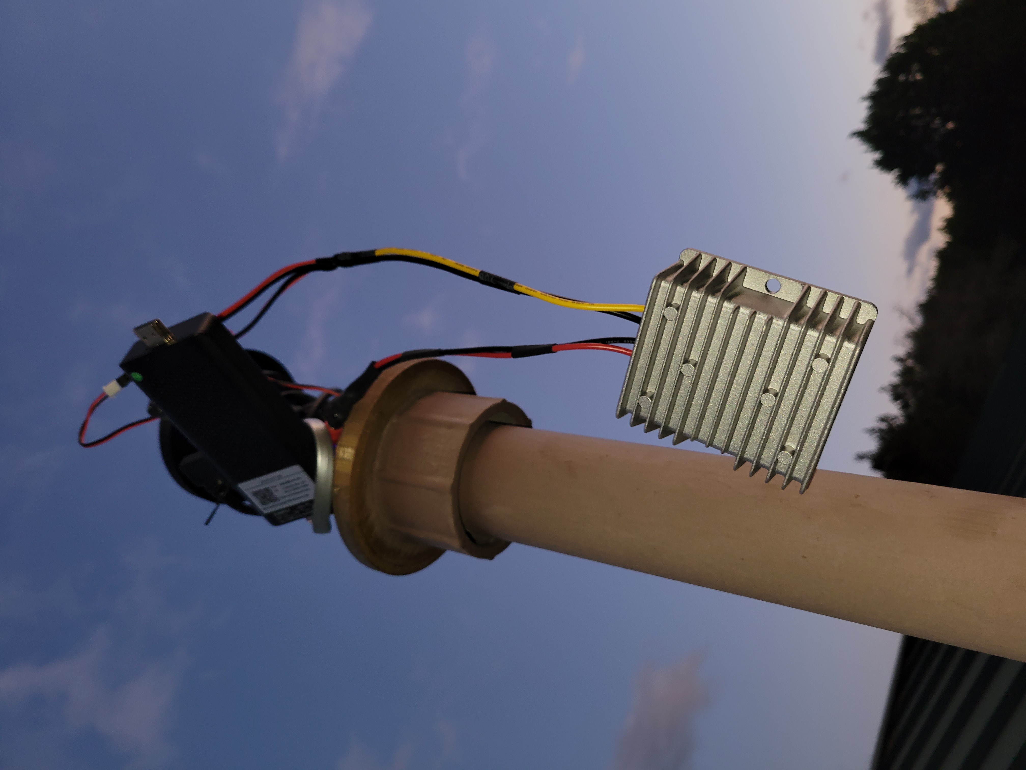
Rather than removing the NexStar GPS from the observatory, I rigged up a voltage regulator so I could plug the NXW434 into my NexStar 8SE mount. (Ignore all the other chips stored on the breadboard.  They’re just stored there from old projects!)  This allowed me to hook up my oscilloscope so I could monitor the communication and confirm what each pin was actually doing.

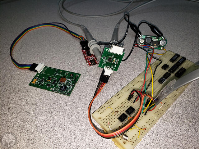
So what I had already suspected, then determined with the oscilloscope and finally confirmed looking at the CN16 wiring, is that the four wire interface on the NXW434 is 5V power, ground, the drop/busy line, and a combined TX/RX line.  It’s NOT separate TX and RX lines as you might think from Barry’s repository.  That’s why Miro’s AVX design works with a single wire.  It turns out the hand controller still reads the GPS fine without the busy line being pulled low.  It’s just that anything else (e.g. a serial or Wi-Fi interface) could potentially attempt to access the interface at the same time and cause a collision since the busy line isn’t low.

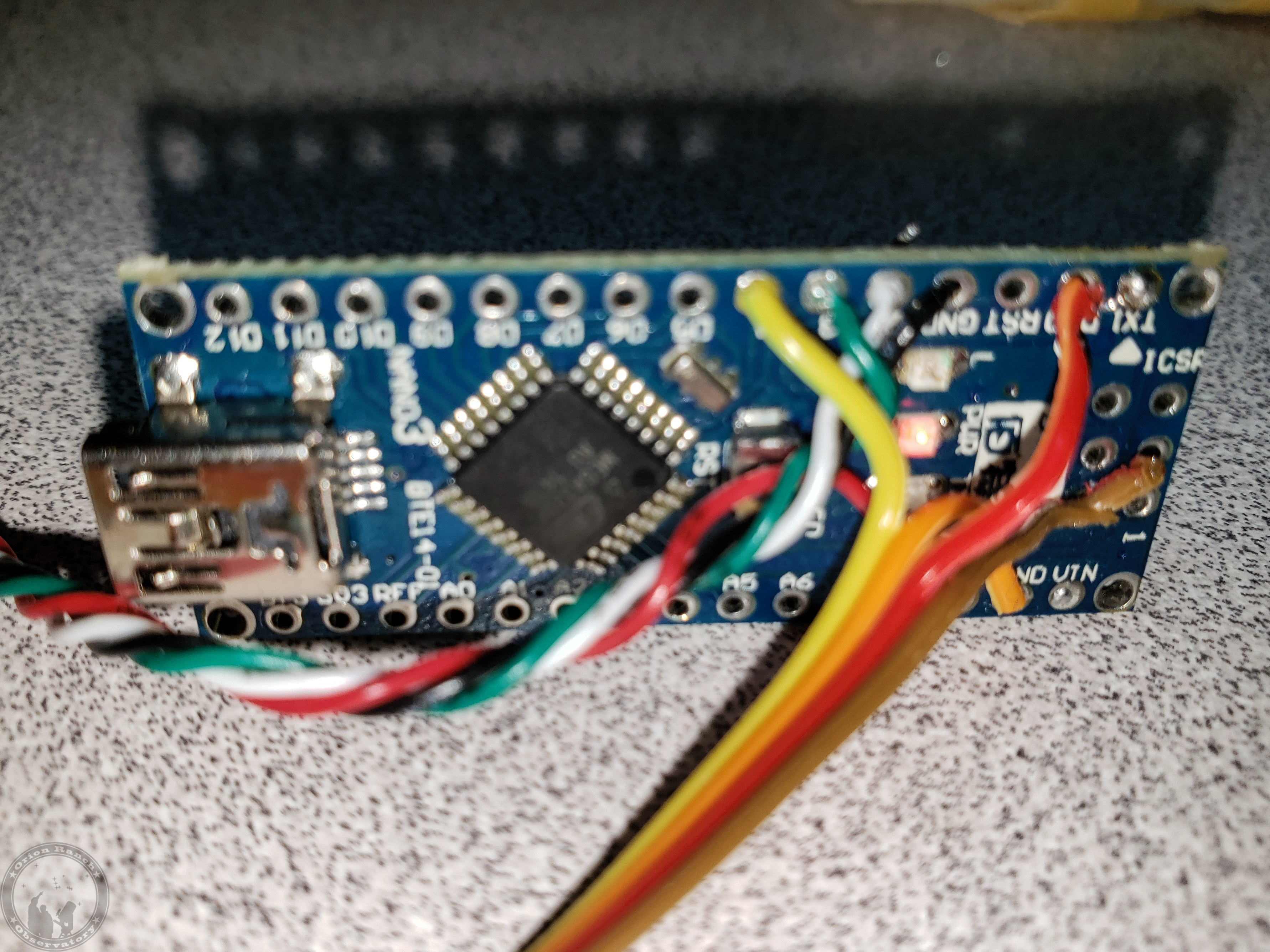
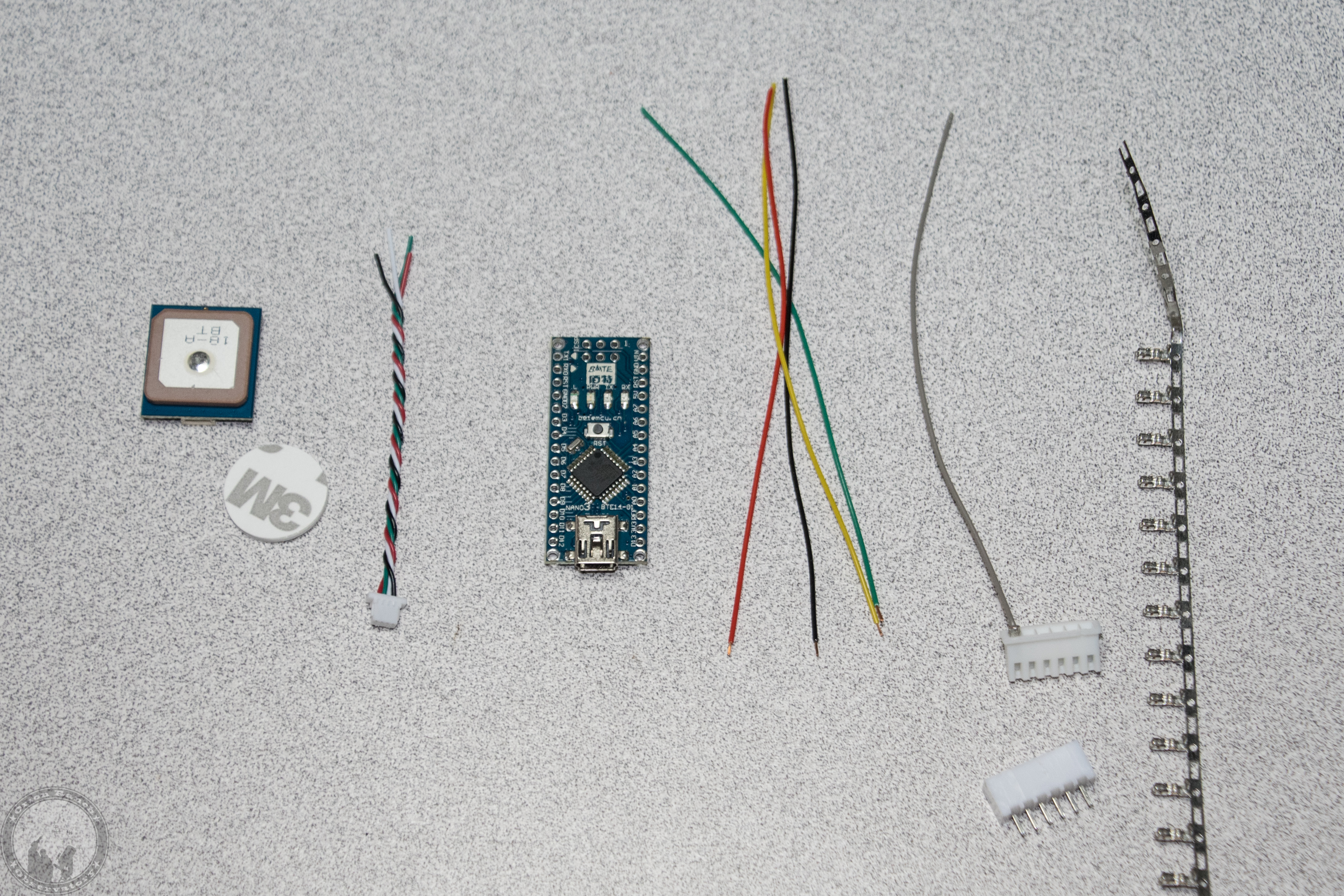
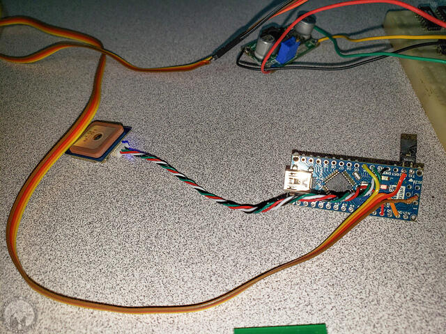
Here’s my Arduino GPS on the test jig.  The BN-220 GNSS module on the left is connected to the Arduino Nano on the right. The jumper temporarily connects serial TX and RX pins, while allowing me to disconnect and reconnect the USB serial port for programming.  

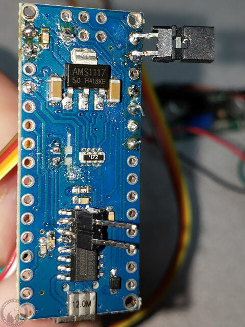
A look at the back side shows more modifications.  The resistors in the middle had to be removed because they connect the CH430 (or FT232) to the serial port on the Atmel ATmega processor. (Funny that Atmel was bought by Microchip who makes the PIC processors!) The resistors are relatively low values, but enough so that if you hook up a normal serial TTL connection to the Atmega you can still drive the lines high or low against the signal from the USB to serial adapter.  However, if you were to leave them on and connect to the common buss on the NexStars, they’d still drive the line and cause Error 16 and 17 when the hand controller starts up and tries to talk to the motor controller.  However, I still needed jumpers for debugging, and started with them on the surface mount pads, but they pulled off quickly. Now they’re directly on the pins.  Of course this same arrangement could have been used with an external USB adapter, or you could use an Ardunio mini with separate adapter like Miro’s setup.

Here’s a closeup of the wiring after removing all the jumpers (after programming it first!).  As you can see, no additional circuitry is required.  The schematic for this setup can be found here.  Note that I might have rearranged the location of the drop line vs. the GPS software serial port had I not already soldered up the GPS connection to match that of the previous designs.

On the back side you can see the solder bridge between TX and RX after removing the jumpers.

I’ll add picture of the installation later, but the BN-220 module with attach directly on the double-stick tape that I pulled the active GPS antenna off of.

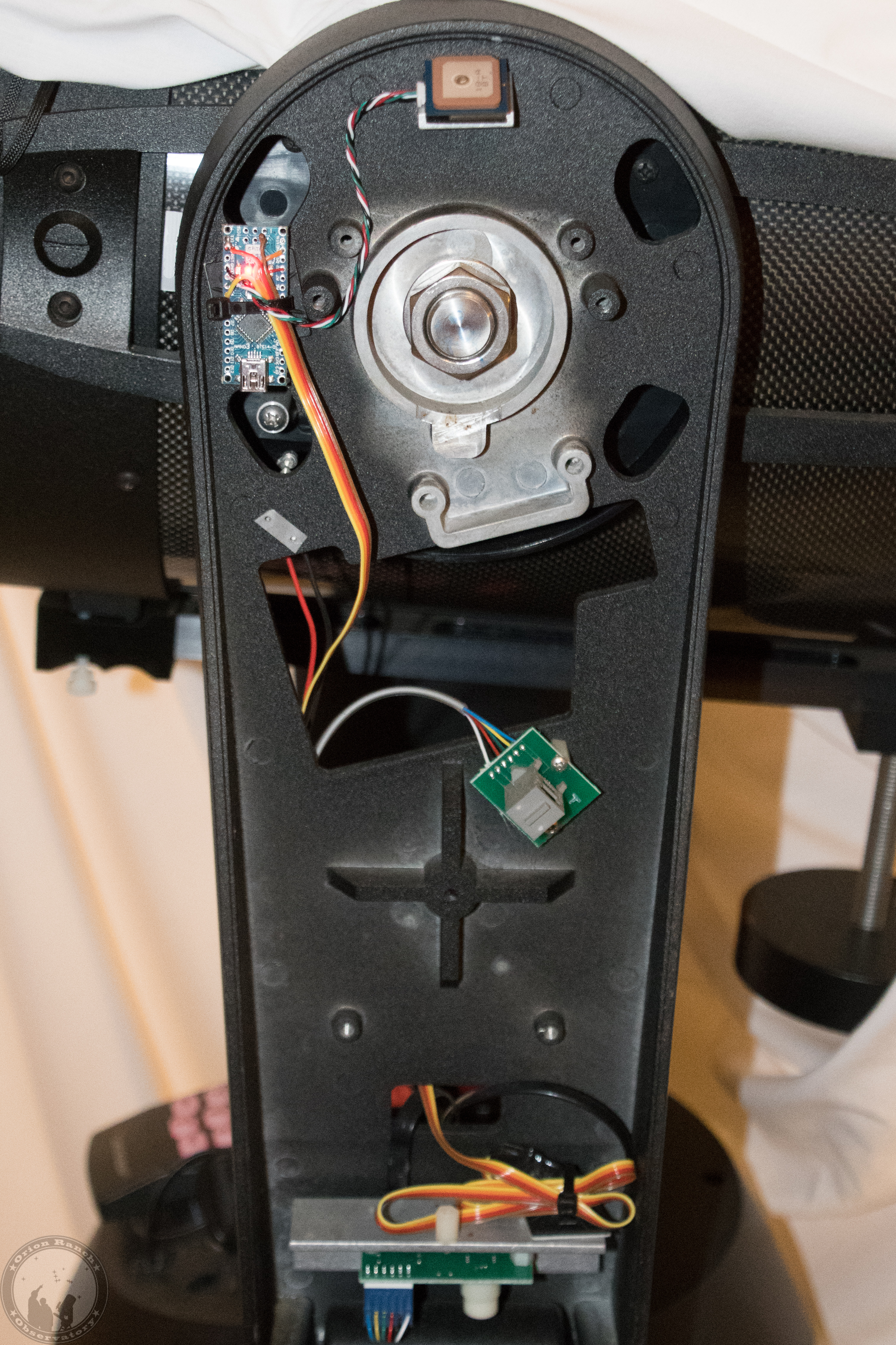
The Arduino and wire will then route down to the connector at the bottom of the fork arm.

Note that the exact same firmware and circuit board setup can be used to connect to the AUX port on any Celestron mount.  Simply feed the +12V line into the Vin pin of the Arduino Nano.  You can find the schematic in my repository here.  At this point I’m debating turning my NexStar 8SE into the (presumably) first NexStar GPS 8SE, adding this mod internally.  That way I don’t have to fool with the CN16 anymore.

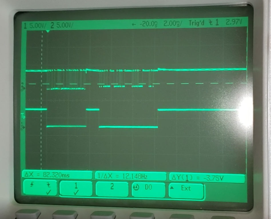
I’ll be posting a video of the testing when I have the chance, but here’s a screen shot from the oscilloscope.  This is showing a transaction between the hand controller and motor control board.  The top trace is the serial communication.  The bottom is the drop line, presumably named that because you drop it low to indicate busy.  

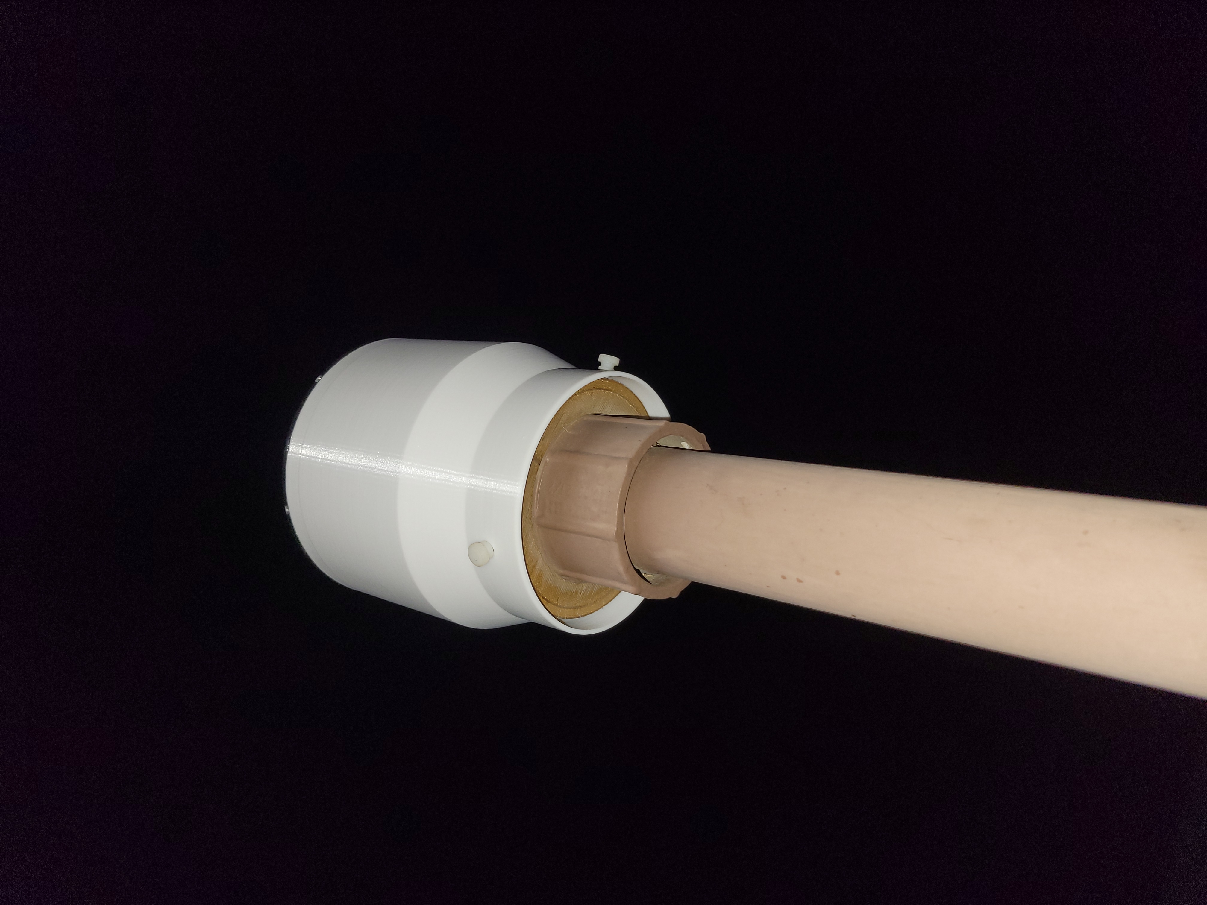
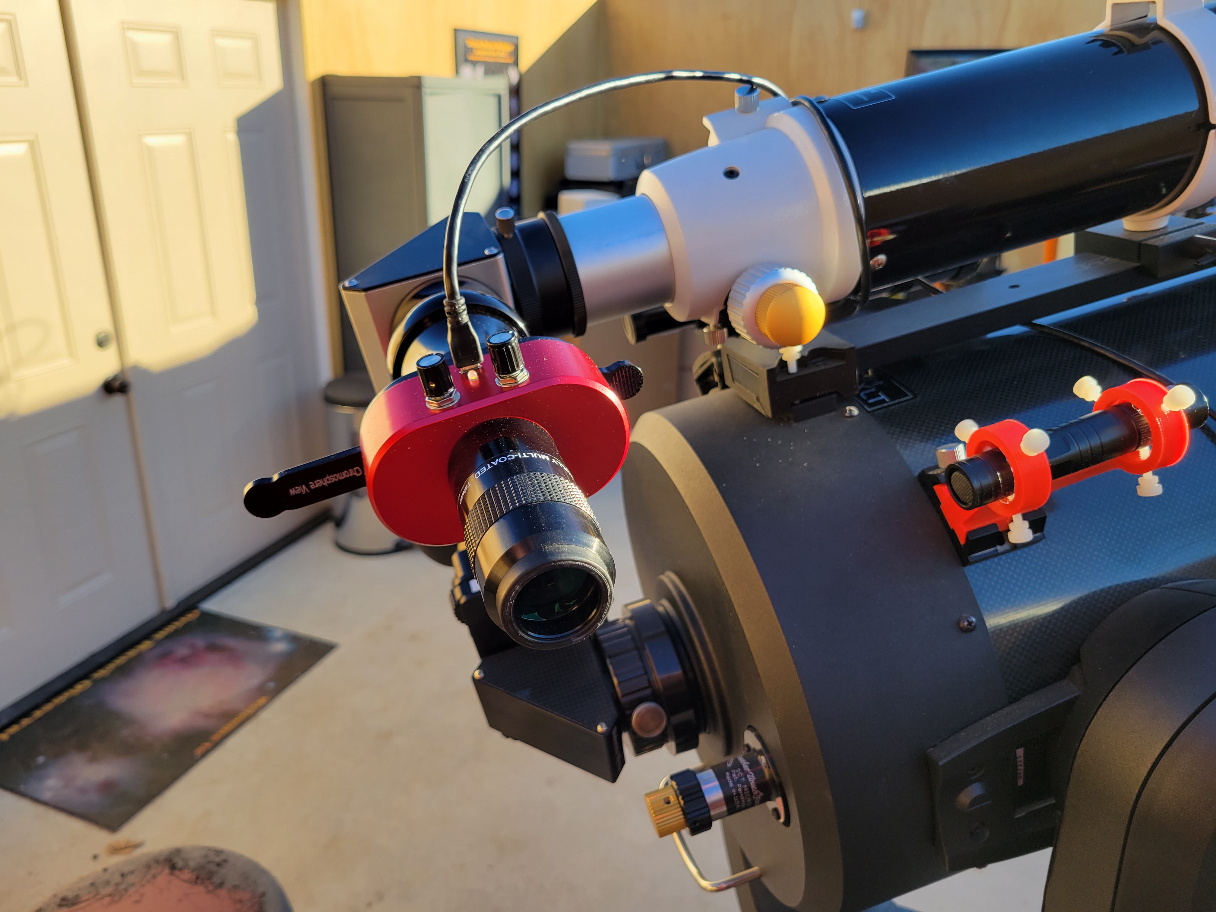
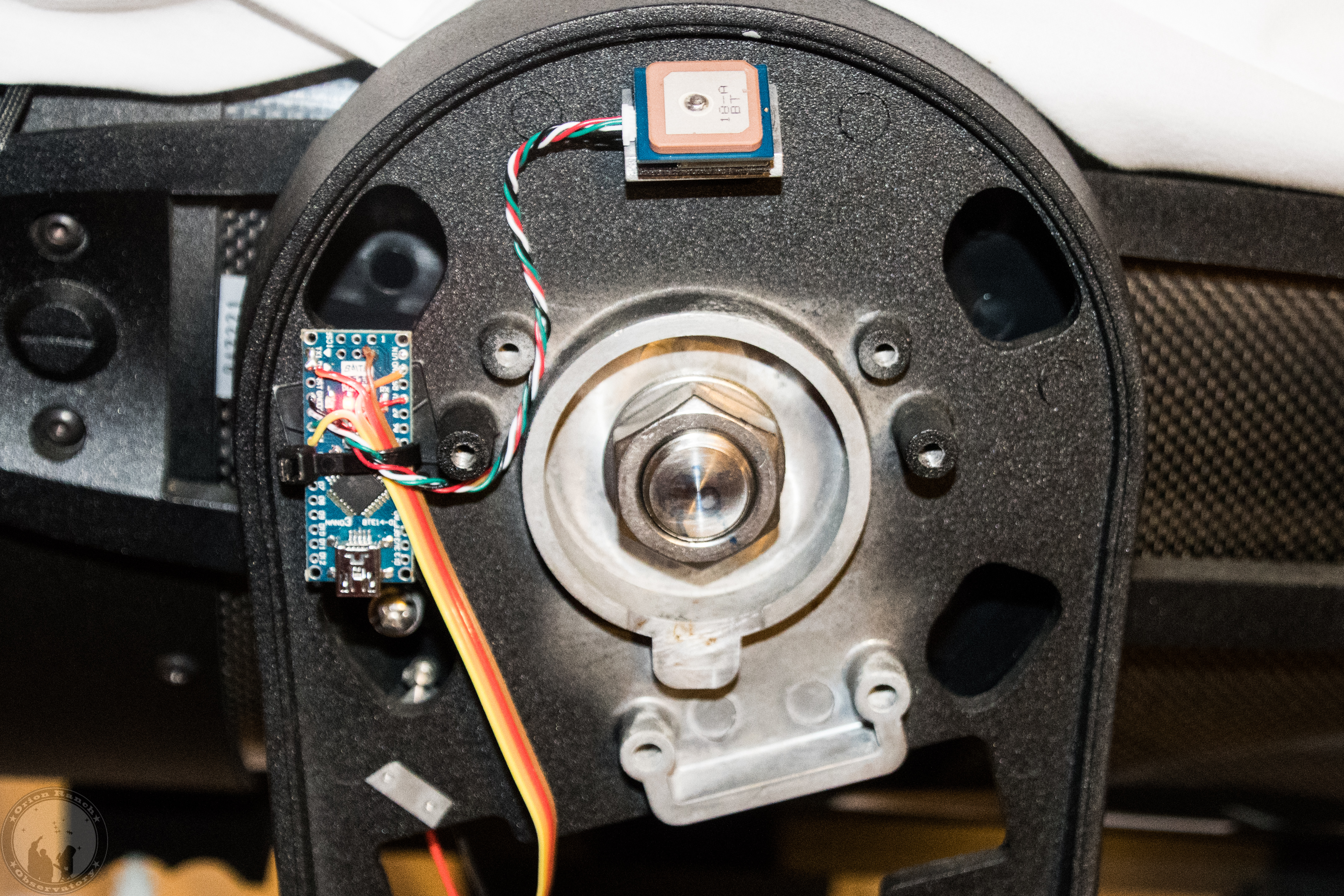
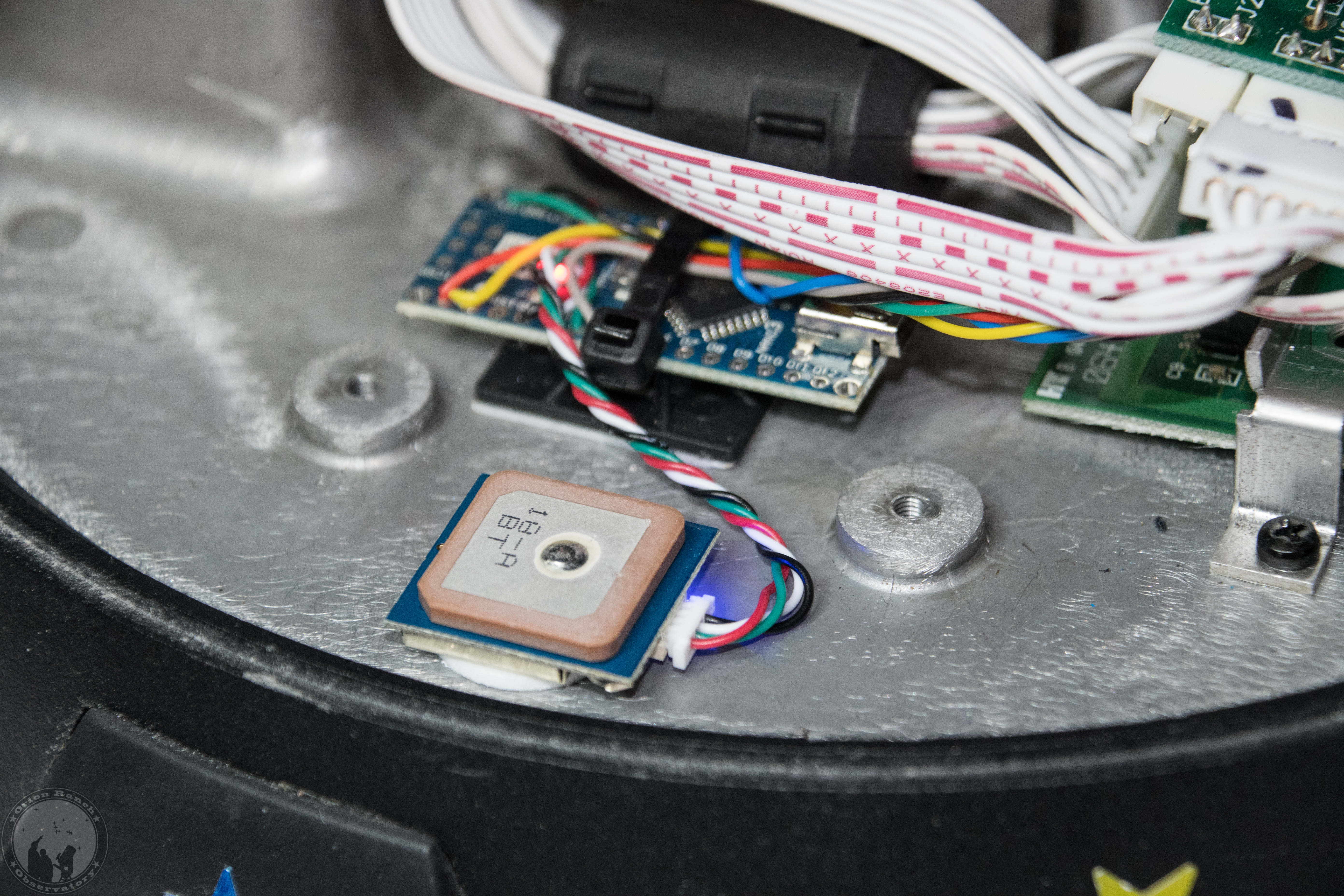
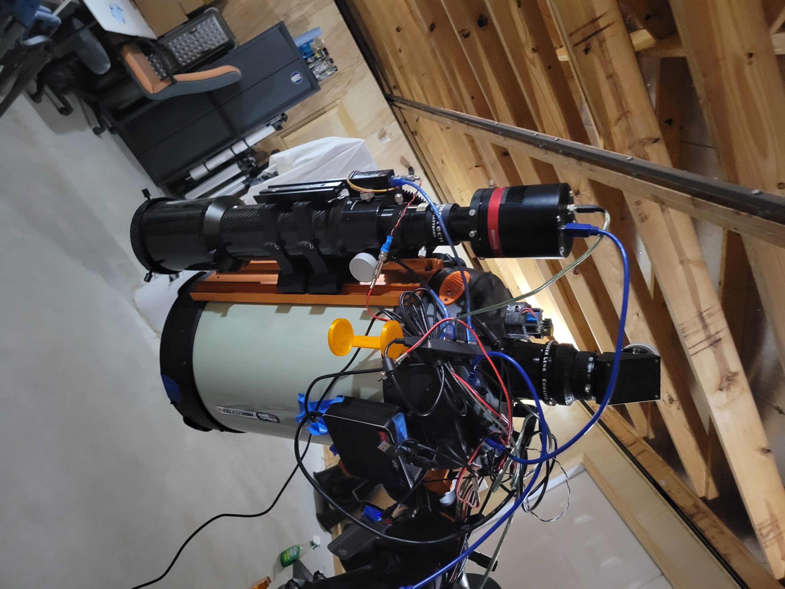
After installing the upgrade in my NexStar GPS, this is what it looks like.

I attached the GPS module directly to the previous sticky tape and used a tie-wrap pad to attach the Arduino nearby. I had made more than enough cable to reach the connector, but went ahead and left it long, which meant bundling at the end with another tie wrap sticky pad. I went ahead and routed behind the arm like the RF cable had run to the old GPS module.

The modification works fine, although I can actually see the blue GPS LED shining through cracks in the case, so I might get in there and cover it up someday.  

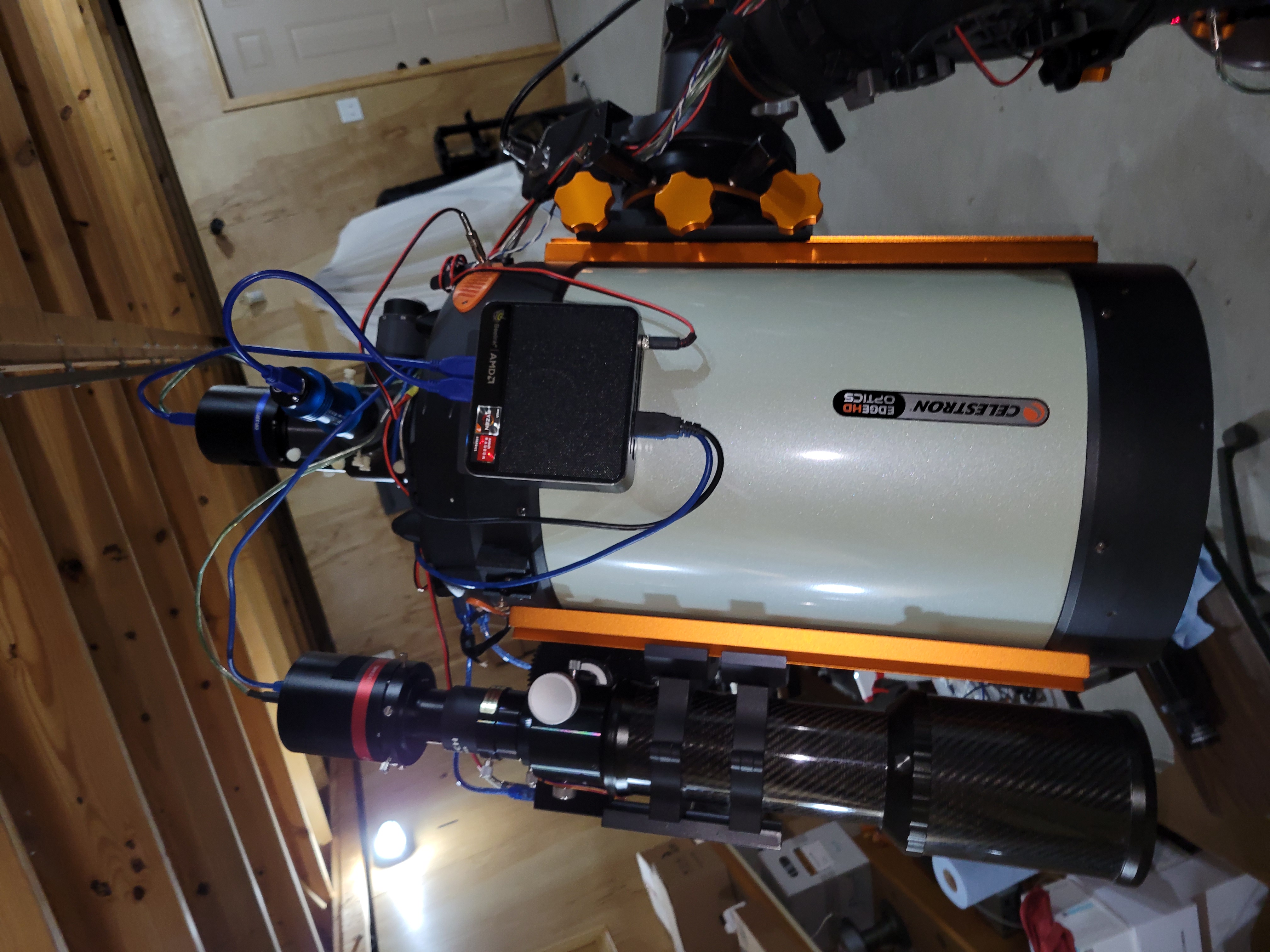
I also decided to order another BN-220 and quickly built an internal GPS modification for my 8SE. Works great! I would hazard a guess that this is the world’s first NexStar GPS 8SE! 

I created a jumper to tap in to the hand control connector on the serial board so that I didn’t have to modify any of the internal parts.

The body of the arm is all metal, so I had to install the GPS in the base, but it works fine there.

At any rate, hopefully all this will help others who want to make this mod.  
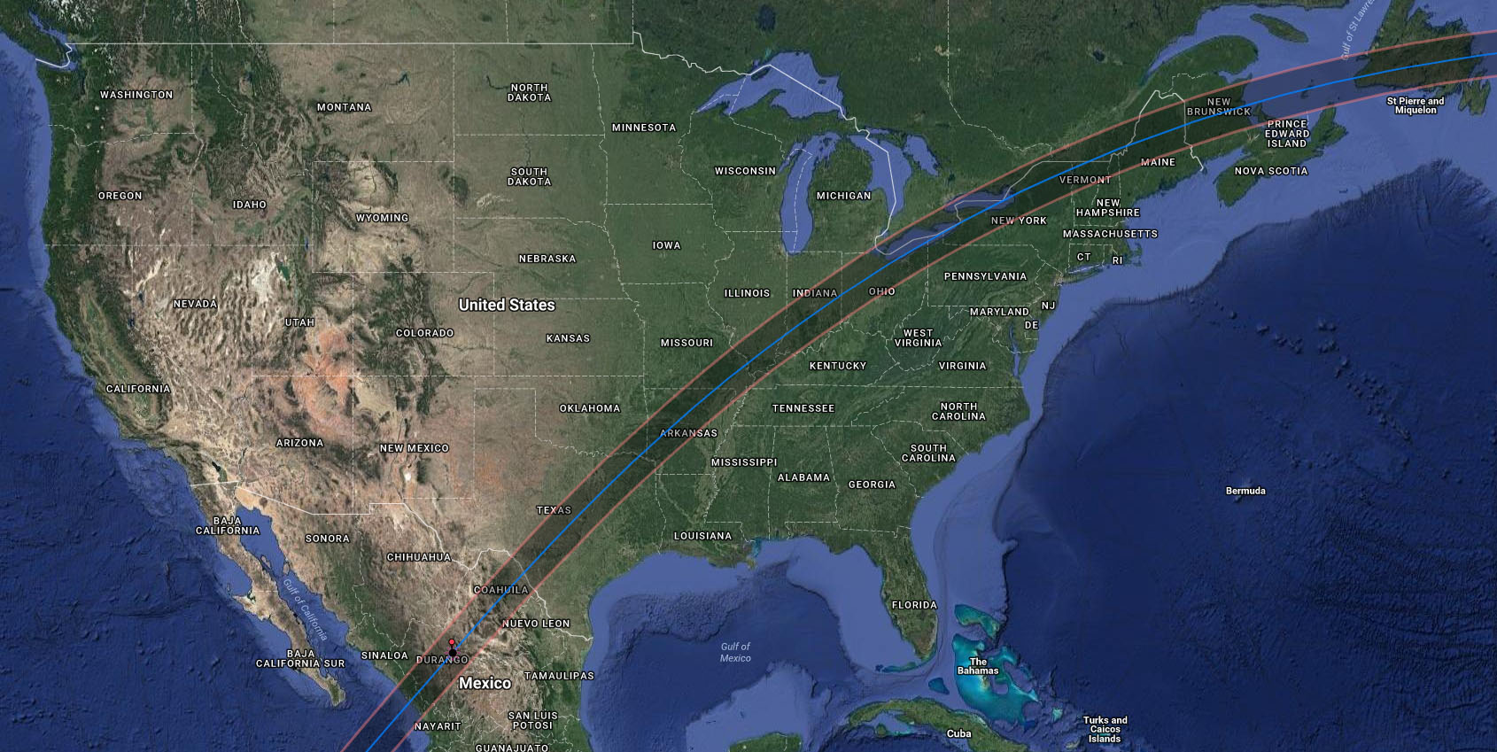
Posted in Uncategorized | 2 Comments

Upgrade Complete!

We’re now running on the latest versions of Gallery 3, PHP, and WordPress, and everything seems to be working fine. There are some glitches in a couple of Gallery modules, but none that appear to affect the user experience. I’ll work on fixing those in the background in the coming weeks. Enjoy the website!

Posted in Uncategorized | Leave a comment

Upgrading Photo Gallery

Well, it’s been a long time coming, but I’m going to bite the bullet and upgrade my Gallery 3 based photo gallery V3.09 to the new “Gallery Revival” V3.10. In 2015, the development on the Gallery 3 project (galleryproject.org) ended and the support site was locked down. In an effort to maintain support for users like myself who were happy with Gallery 3 but needed to make tweaks and enhancements, I started the Gallery 3 Yahoo group. This has helped numerous users keep their Gallery 3 installations plugging along, but web technology, security issues, and the like have changed the environment considerably since the Gallery 3 development project was started many years ago. Thankfully, at the beginning of this year, an industrious member of the Yahoo group released a new version of the Gallery software that brings it up to date with some of the latest web functions. If all goes well, it won’t change the way anything works from the user side, but from the web server, it will allow running the latest, safest version of all server software. So, I plan to make the migration “as soon as I can.” It shouldn’t take long once I get started, but if I don’t get started this evening, it might be a few days before I get to it. At any rate, I’ll post again when the change has been made. Let me know if you encounter any problems!

Posted in Uncategorized | Leave a comment

Visit my YouTube channel!

I finally gave in and started my own YouTube channel for various videos I’ve been putting together. While I’ve typically done photographic records that I could come back and document with text, I found I wasn’t doing that very often, even though I had tons of pictures available. Since the public trend is toward video “how-to” guides, with the recent purchase of a large 3D printer kit that was not documented properly at release, I decided to try my hand at video logs instead of just photographic logs. They may be a bit rough, and editing still takes just as long as documenting a bunch of photos, but they’re a start. The only downside is that my photographic documentation of some of these projects has suffered due to the concentration on video.

At any rate, I’ve set up my YouTube channel at the previous link and moved a couple of my astronomy videos there, along with other videos on the 3D printer and other topics. I’ll probably still upload appropriate videos here in parallel, but please take a look and subscribe if you’re interested.

Thanks,

Michael

Posted in Uncategorized | Leave a comment

Dyson’s Radio, Free from Friday through Sunday, February 24th, 2019

See the previous post for details on the book. For some reason the originally scheduled sale on Wednesday didn’t fire.

Posted in Uncategorized | Leave a comment

Published My First eBook!

When an amateur astronomer detects a modulated signal in the flash of a nova burst, the race is on to capture and decode the signal before it’s too late.

This science fiction short story is my first self-published eBook through Amazon, although it’s not my first sci-fi short story.  Of course I’ve written plenty of technical magazine articles and papers, not to mention untold numbers of online posts, articles, how-tos, etc., but fiction is something that, beyond not just having time to write, I never felt I could dedicate the time to it, much less carry a story to completion.  Thus, the most I’ve been willing to shoot for is a couple of short stories.

Leaving out some stories I wrote back in high school and college that I’d love to dust off if I could find them, my first relatively contemporary short story was “Goodbye Mr. Smith”, a sad and extremely short story from a sad time in my life, that surprisingly has components in common with the end of Dyson’s Radio.  In “A Dark Matter”  (currently awaiting a response from Analog)  I discovered a narrative approach that worked well for me.  Thus, when I came up with the idea for Dyson’s Radio, I knew exactly what I needed to say and where I needed to end up.  However, even I didn’t know everything I’d discover along the way.  The story ended up being quite a bit longer than I expected.  It also became so current and topical that I decided it couldn’t wait for a long editorial review process.  After a quick response from Asimov saying they wouldn’t be able to do it in time, I decided to go for direct publication to be sure that people had a chance to read it as it was intended to be experienced.

While I could easily have padded the story considerably by explaining many of the things mentioned, it was really written for the true space geeks among us who will immediately understand most of the references that the characters already know.  Thus, if you’re here it’s probably because you already love the idea of space and space exploration and don’t need anyone talking down to you about it.  However, there is a tremendous amount of background information I put together to keep the story plausible, and I envision writing a technical article on “Building Dyson’s Radio” to be published sometime in the future.  And who knows.  If I get brave enough I may even revisit this world.  There’s certainly plenty to build on, but I just don’t know if I’m up to the challenge!

And if you’re lucky enough to be reading this today (December 6th, 2018), it’s currently free on Amazon.  Merry Christmas!

Posted in Uncategorized | Leave a comment

I think I’m done!

I started writing this post just over a year ago and then realized I wasn’t done, so I didn’t get much further than a title and a first line that I tossed.  However, at this point I think I’m about as done as I’m going to get with processing of images related to last year’s solar eclipse.  I’d originally intended to design another poster or two, but at the moment I have too many other things going on and don’t feel all that creative in that direction.  Perhaps before the next total eclipse rolls around in 2024 I’ll go back and look at it again.

At any rate, what I have accomplished just recently was to finally go back and finish a process I’d started last year when I discovered I’d captured the amazing lunar umbra shadow on the clouds in the following image.  Since I apparently never made a blog post on THAT I’ll post it here too.  In fact, it turns out that I never posted much of anything here about all the processed images from the eclipse, but I did make a few posts on Cloudy Nights.

So you can see all my images and time lapse video from the event, and details on the preparations and photography of the actual eclipse, but the one thing that took me quite a while to do (and even longer to go back and finish) was manually recording the automatic exposure settings of every frame of my time lapse video and then writing a script to adjust the exposure to back those out of each frame in Photoshop so that it’s as though the camera was set with a fixed exposure during the entire eclipse.  While no computer monitor or file format is sufficient to cover the real dynamic range from full sunlight to evening night sky, this video will give you an idea of the change in illumination throughout the duration of the eclipse.  The bright sky is completely blown out, but if you watch the landscape and foreground you can see things getting darker during the progression of the partial eclipse before things go almost completely black at totality.  The goal is to give you an idea of what totality really felt like.  Note you can still see the shadow of the moon against the sunlit clouds along the horizon.  There are two versions of this in the solar eclipse party folder linked above, but this one has the actual eclipse progression overlaid in the corner once the image capturing starts at about 30 seconds into the video.  You can compare the darkening of the sky to the progress of the Moon across the Sun.  I hope you enjoy it!


Posted in Uncategorized | 1 Comment

NexStarEquatorial Driver Released for Testing

In my ongoing quest to fully automate my observatory, I’ve been developing a number of ASCOM standard drivers for most of my custom equipment. The one thing I’ve wanted to do for some time is to find an alternative to Celestron’s NexRemote software that has to be manually started and brought out of hibernation and then manually put into hibernation and shut down before powering off the telescope. Even then, it was common for the NexRemote software to hang up and lose alignment often requiring a good half an hour or more to attempt to re-do an alignment remotely.  It never made sense to me that with the availability of plate solving to determine exactly where the telescope OTA was pointing that I couldn’t just enter the current coordinates and have the scope aligned, given a good polar alignment of the mount.

What I needed was a software/driver that would automatically restore the motor position information on startup and automatically stop the drive and save the position information  on shutdown.  Not to mention, having the ability to take a picture and quickly align the mount to the current RA/DEC coordinates.  Given that there was no other alternative forthcoming, I finally decide to go ahead and develop my own solution.  Rather than writing another stand-alone program to take the place of NexRemote, which is just an emulator that runs standard hand control firmware, it made more sense just to build all the required functionality from the hand controller into a single telescope interface driver that could be used by any software built to use the ASCOM standard.  Thus was born the NexStarEquatorial ASCOM driver.

Essentially I’ve implemented the important components of a NexStar hand controller directly into an ASCOM driver that communicates with the motor controllers directly through the PC or AUX port of the mount.  Alternatively, the driver also supports communication through the serial port adapter in the base of the NexStar hand controller, although like NexRemote, it does not actually use the hand controller for anything other than the interface.  The driver automatically saves and restores the current position of the mount on exit so that even if the mount is powered down in between sessions, when the driver starts back up, everything’s still where it was.

This driver is targeted towards full system automation and imaging, so it only supports the NexStar mounts in equatorial mode (thus the name).  It also relies heavily on imaging software capable of plate solving and aligning automatically (i.e. something like Sequence Generator Pro).  With a good polar alignment and starting point, there’s no need to do any sort of manual alignment at all, but it does support manual entry of coordinates from a plate solve to get the current reference if desired.  I actually don’t use it because SGP handles that all for me.

By limiting the functionality to equatorial mounted scopes , including German Equatorial Mounts (GEMs) like the CGE, CGEM, CGE Pro, etc., and fork mounted telescopes like the NexStar GPS and CPC mounted on polar wedges, the requirements for the driver are greatly simplified.  For a mount that’s perfectly polar aligned, the “azimuth” axis becomes the right ascension (RA) axis and simply needs to run as a clock motor, with one revolution every 24 hours.  The other axis (altitude/elevation for a fork mount) just provides the North/South declination adjustment.  The spherical coordinate system for an equatorial mounted scope is pretty straightforward then, with the current local sidereal time indicating what should be directly overhead along the meridian line dividing the eastern and western halves of the sky.  The azimuth angle relative to the meridian just needs to be converted from 360 degrees to a 24 hour format and offset by that sidereal time to get the current right ascension, although for GEM mounts that also requires an east/west offset of 90 degrees between the axis position and the orientation of the OTA.  The declination axis runs ±90° from the equator, but again for a GEM there’s a positive and negative side to the OTA orientation depending on which side of the pier the OTA is on and which side of the sky it points to.  And of course in the southern hemisphere, the scope is mounted in the opposite direction and all axes have to run backwards.  In all it’s just a pretty basic spherical geometry problem, but getting all the signs and combinations of behavior correct was still a bit tricky.  Some of the Celestron mounts have their own quirks as well, with the CGE Pro (and possibly others) forcing a required 90 degree offset to the definition of “up” on the azimuth axis.  And of course the ASCOM standard has its own quirks.

The following figure is the current setup dialog for configuring the driver.  It sets up the communication method and mount type, as well as the mount location which is critical to the initial determination of the RA/DEC coordinate system.  Subsequent homing and alignment/synchronization steps will set the actual position offsets once connected to the scope.  In addition, ASCOM reports the details on the optical tube assembly, so that information can be entered here as well.  Hovering over each control provides hints as to the function of each setting.

Once the ASCOM compliant client software connects to the scope through the driver, the following hand control paddle is displayed.  The hand controller can be toggled to stay on top or closed and reopened from ORO logo icon in the system tray.  The hand control provides traditional manual positioning control, targeting, position readout, tracking and parking control, as well as basic alignment functions.  No positioning database is provided as that is expected to come from the client software.  Other than an initial homing process to set the reference position of the mount the first time the driver is used, no further manual interaction should be required given suitable client software.

The driver has been made available for beta testing by interested users, and I’ve started this thread on Cloudy Nights for comments and feedback.  I may eventually publish a more detailed manual here in the future, and of course expect to probably add a few more features over time as I have time and the desire to do so.  I hope others will find this as useful as I have so far.  It solves my automation problem amazingly well!

Posted in Uncategorized | 6 Comments