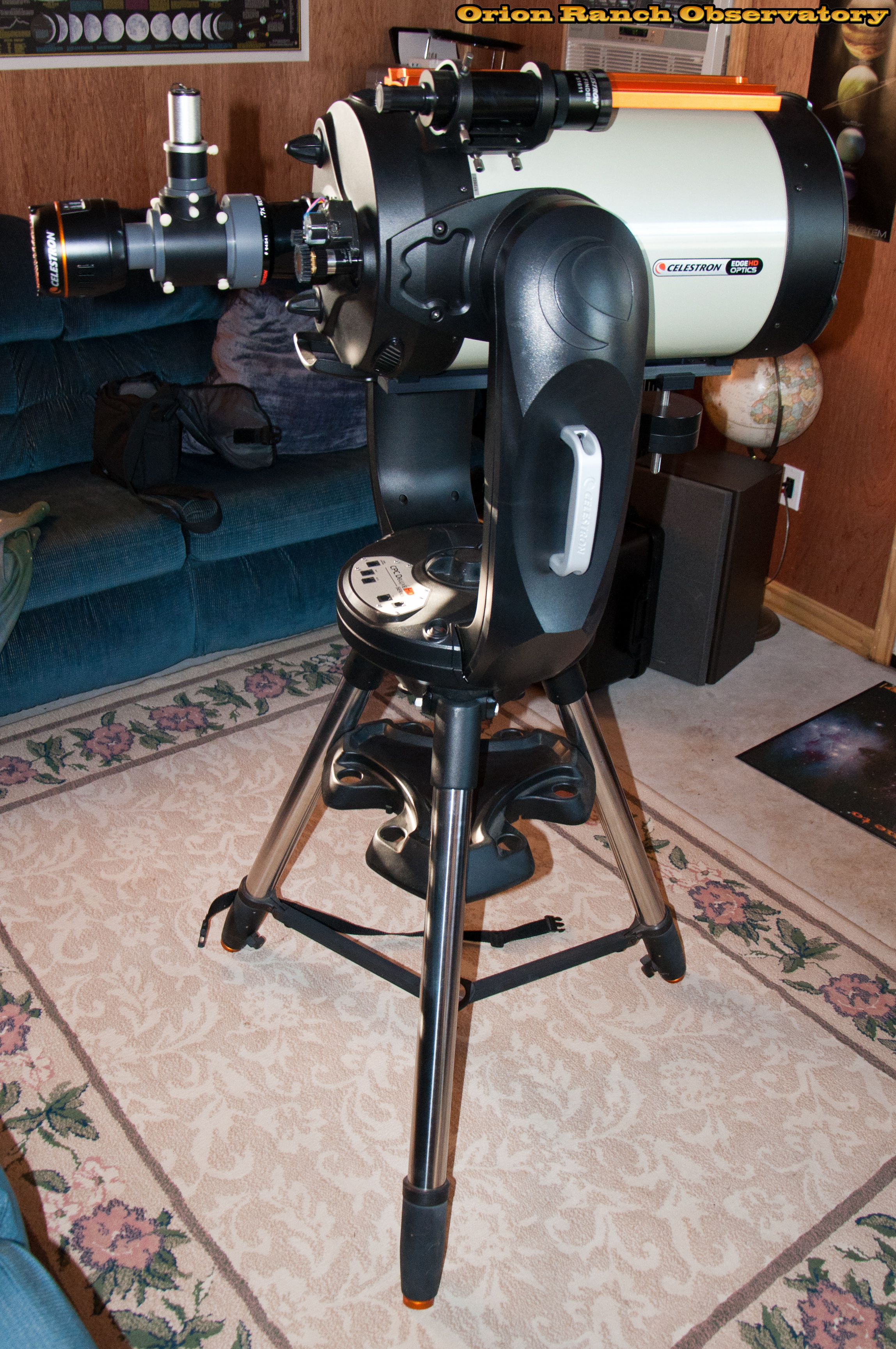
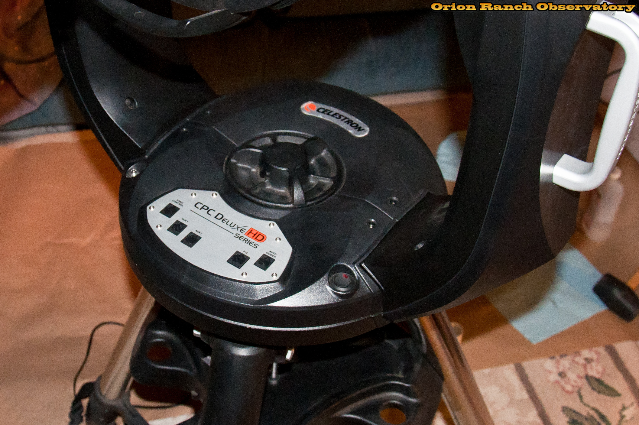
In a somewhat misguided attempt to improve the tracking on my Celestron CPC Deluxe 1100 HD 11″ EdgeHD telescope, I decided to perform the bearing upgrade described by Gary Bennett on the NexStar Resource Site.
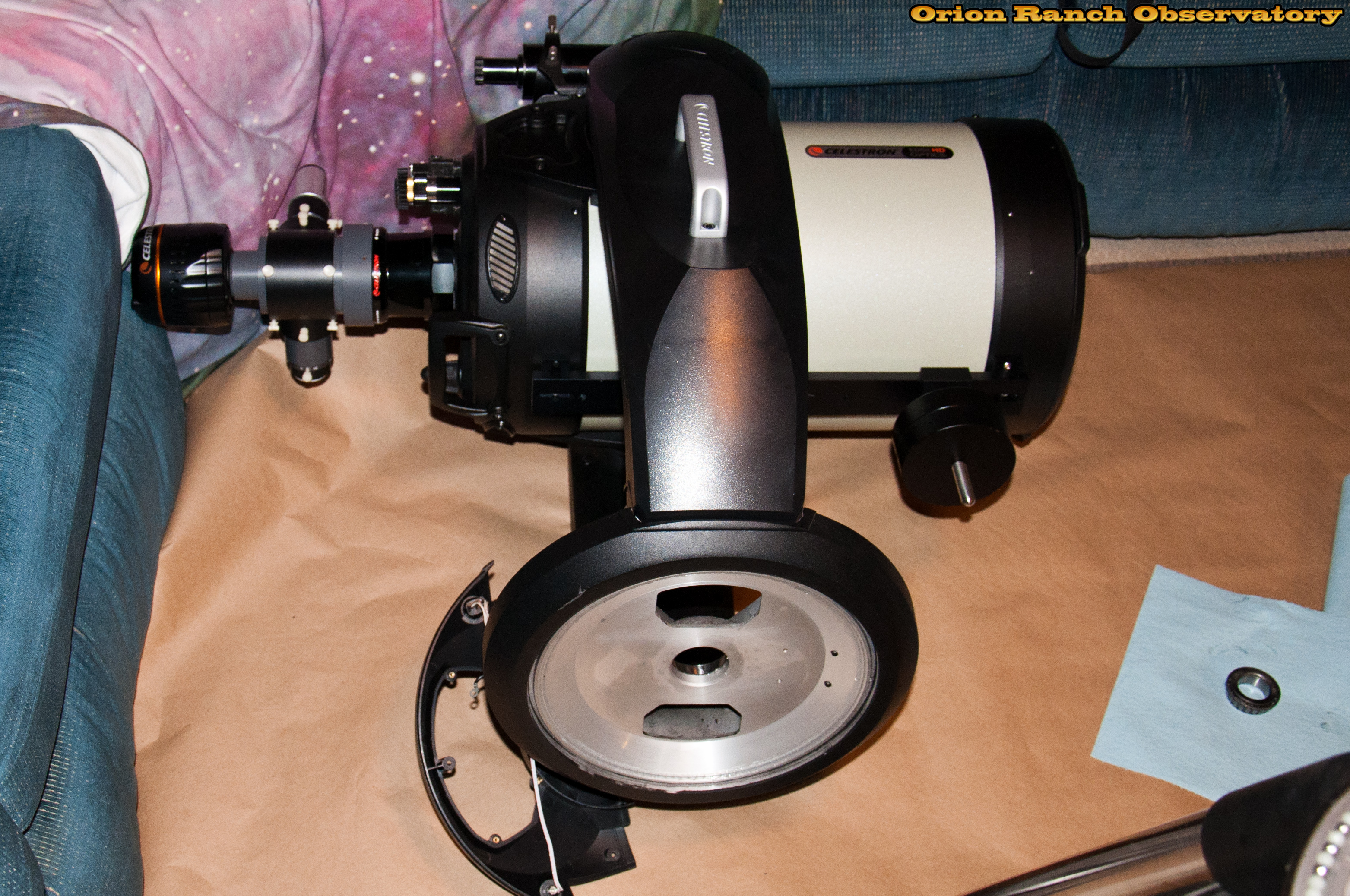
I started by moving the EdgeHD to the tripod in the warm room in order to prepare for the azimuth axis rebuild.
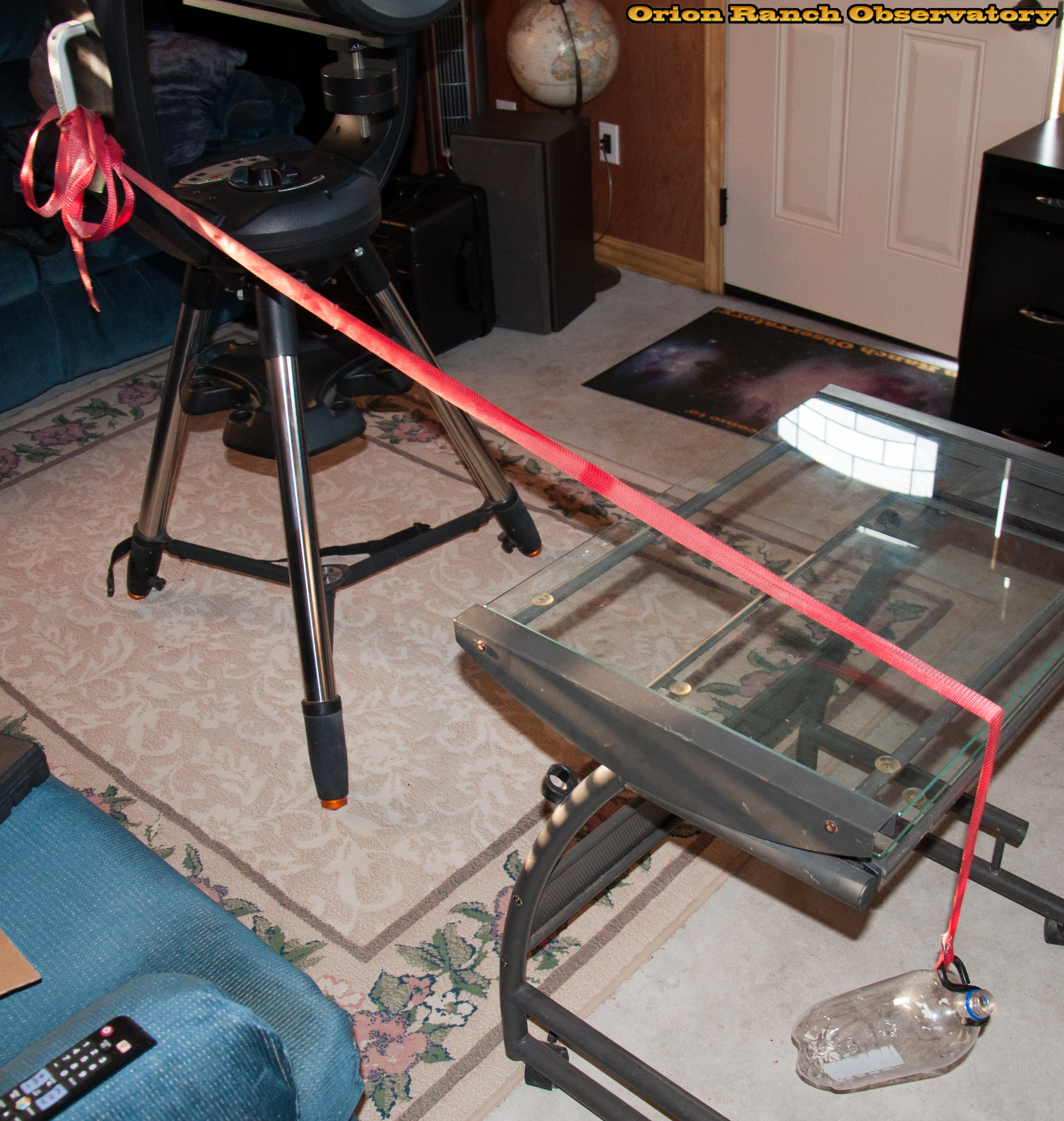
I attempted to measure the force required to rotate the azimuth axis for a before/after test. I didn’t have a force gauge handy, so came up with a pretty simple scheme for using gravity to test for how much weight it took to overcome friction. By determining how much water weight was needed to get the axis to rotate, I could compare after the upgrade. Unfortunately, it turns out most of the friction was from the clutch assembly and not the bearings, so there’s really no way to use this information to determine if I improved anything.
After partially removing the set screw to clear the upper lip of the clutch base, the clutch knob unscrews completely revealing the Teflon pressure plate that lets the knob slip to loosen or tighten the clutch.
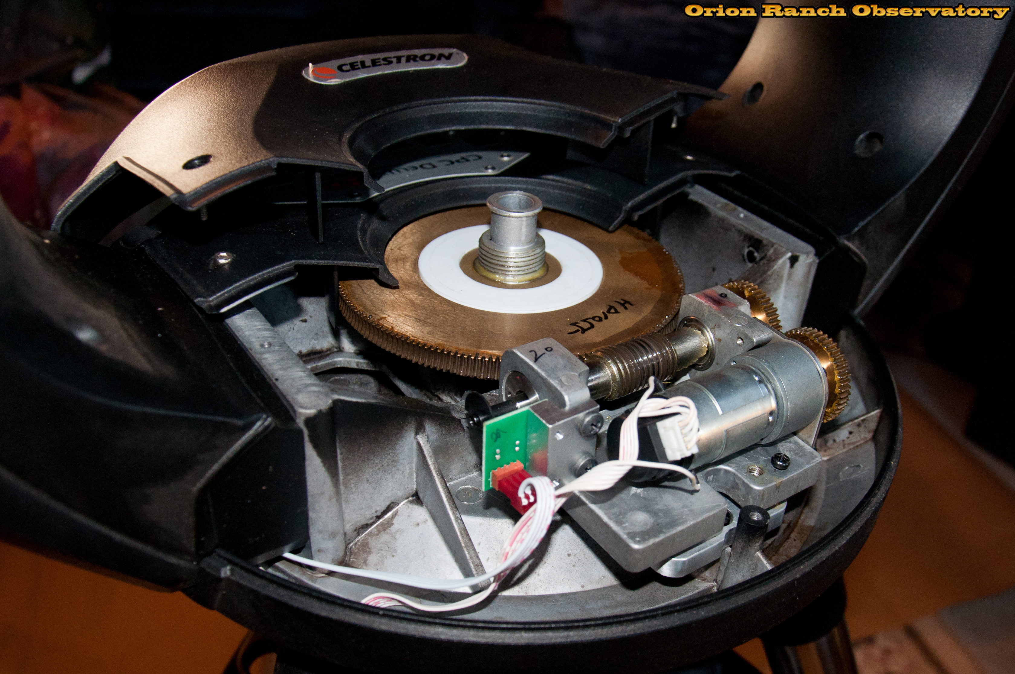
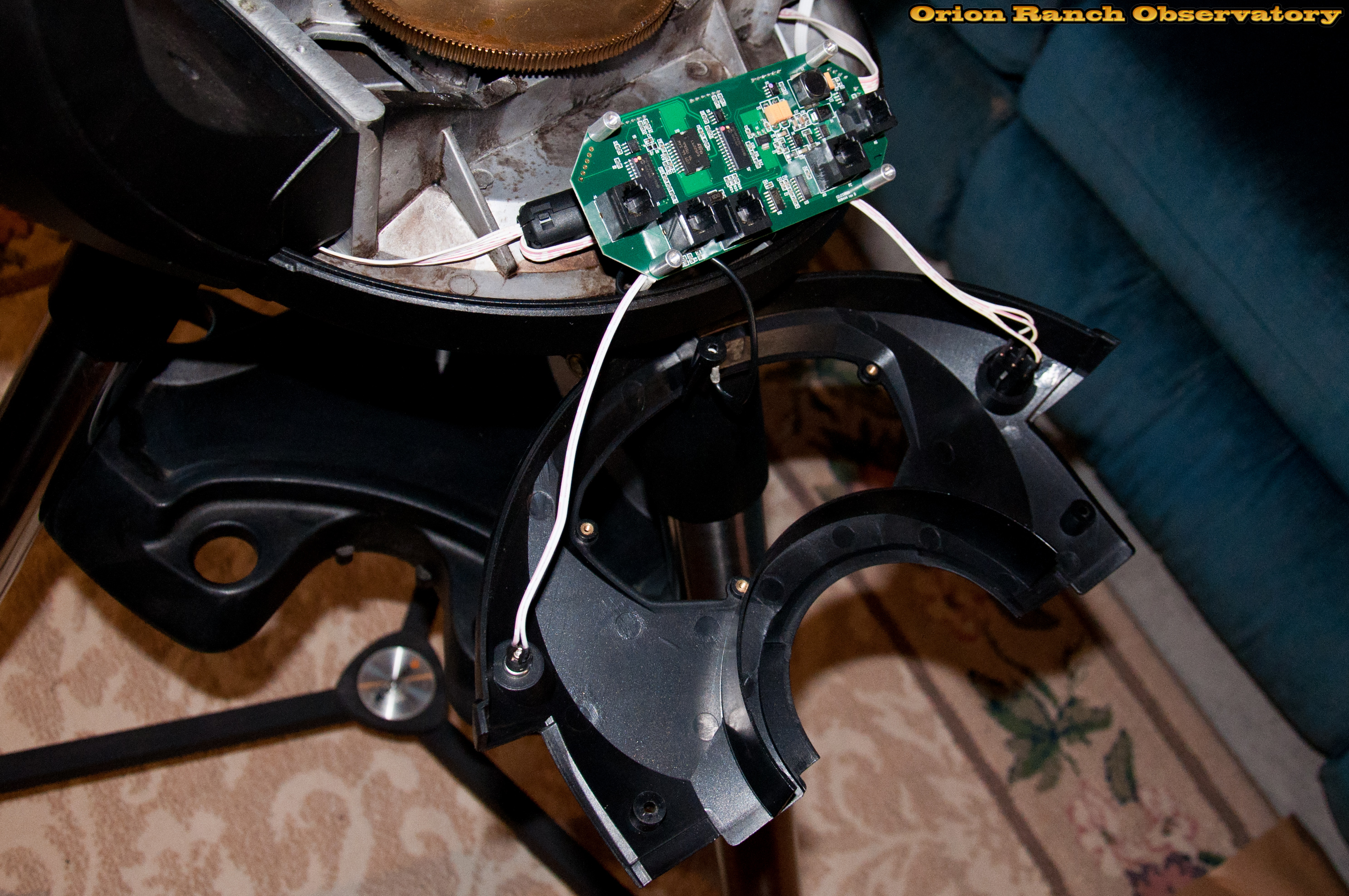
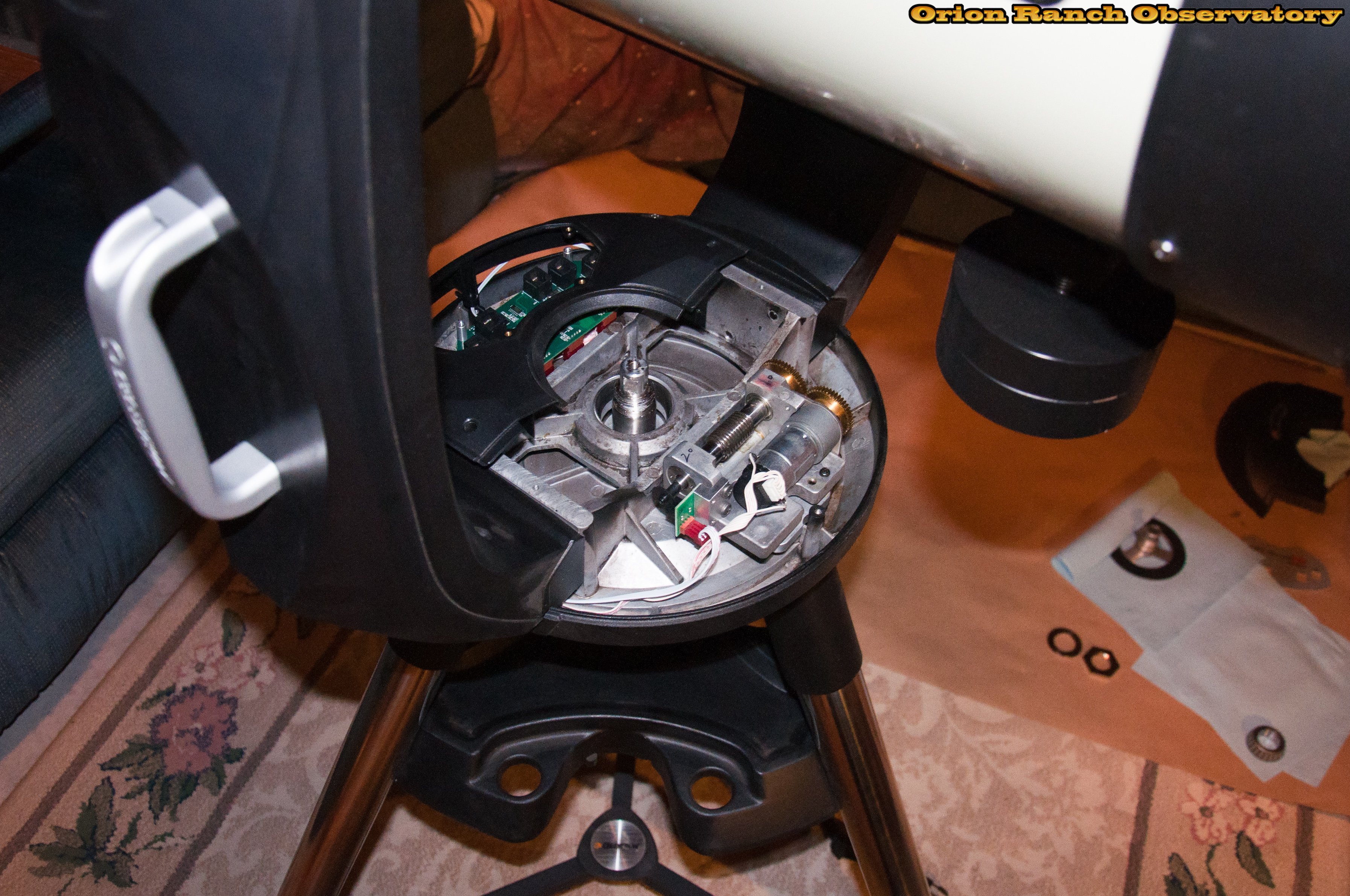
The spur gear servo motor drive turns the worm gear on the far side. You can see the black encoder on the back of the servo and the PEC reference sensor on the main worm gear shaft. The spur gears connecting the motor to the output shaft are typically covered with a shroud. Not sure why my unit doesn’t have it. Also not sure why they need a 1:1 gear vs. finding the space to direct drive the worm and eliminate that additional point of play.
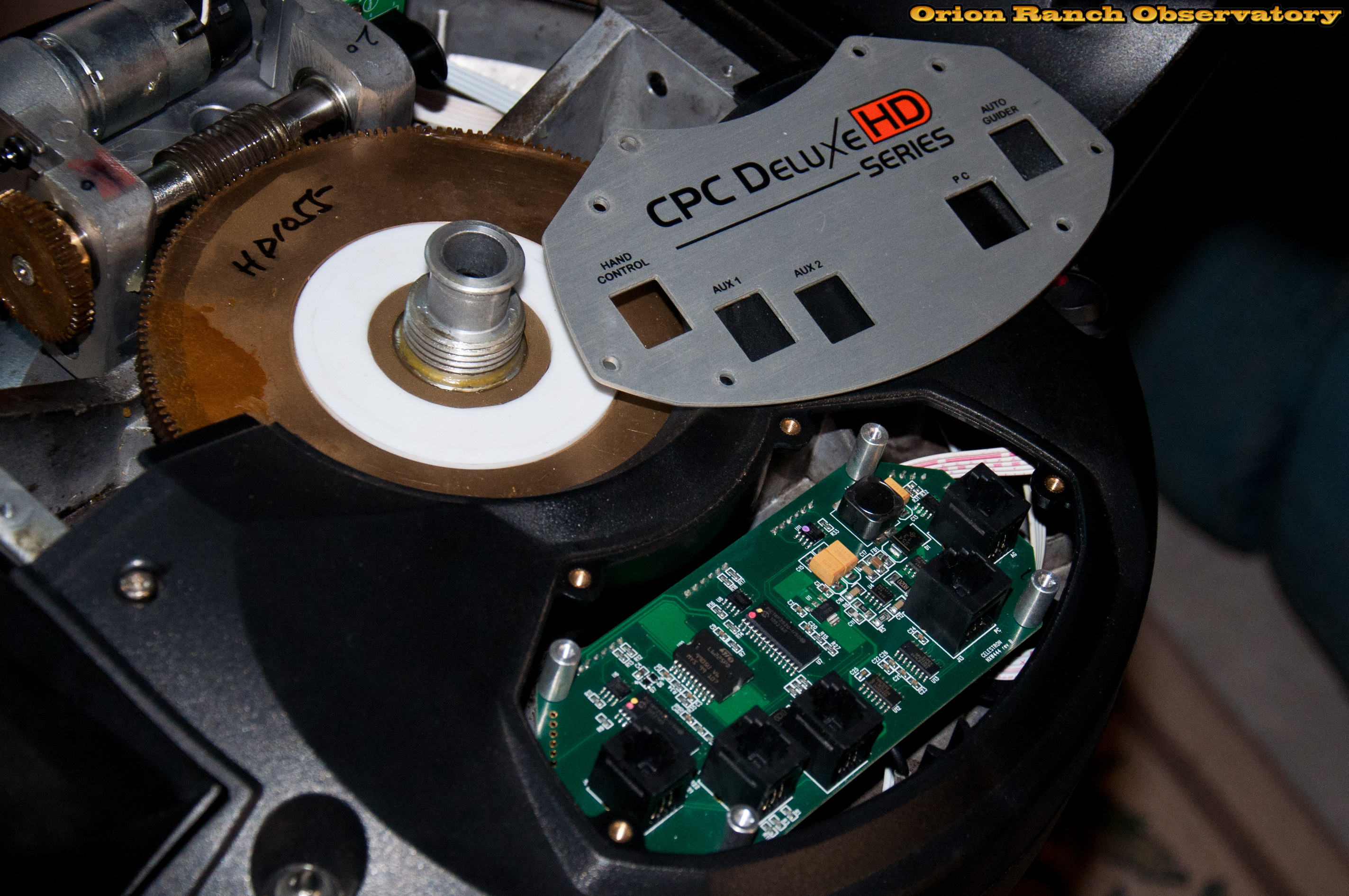
The main board cover plate must be removed to get to the third screw on the front side cover panel. Turns out it’s not necessary to remove ALL the screws. The four screws on a rectangular grid hold the controller PCB to the panel, so removing the four screws along the edges allow removal of both the panel and board. See the re-assembly pictures for more info.
After removing the aluminum cover, I can access the third cover screw. I just left the board and cover hanging rather than having to label all the connections before disconnecting.
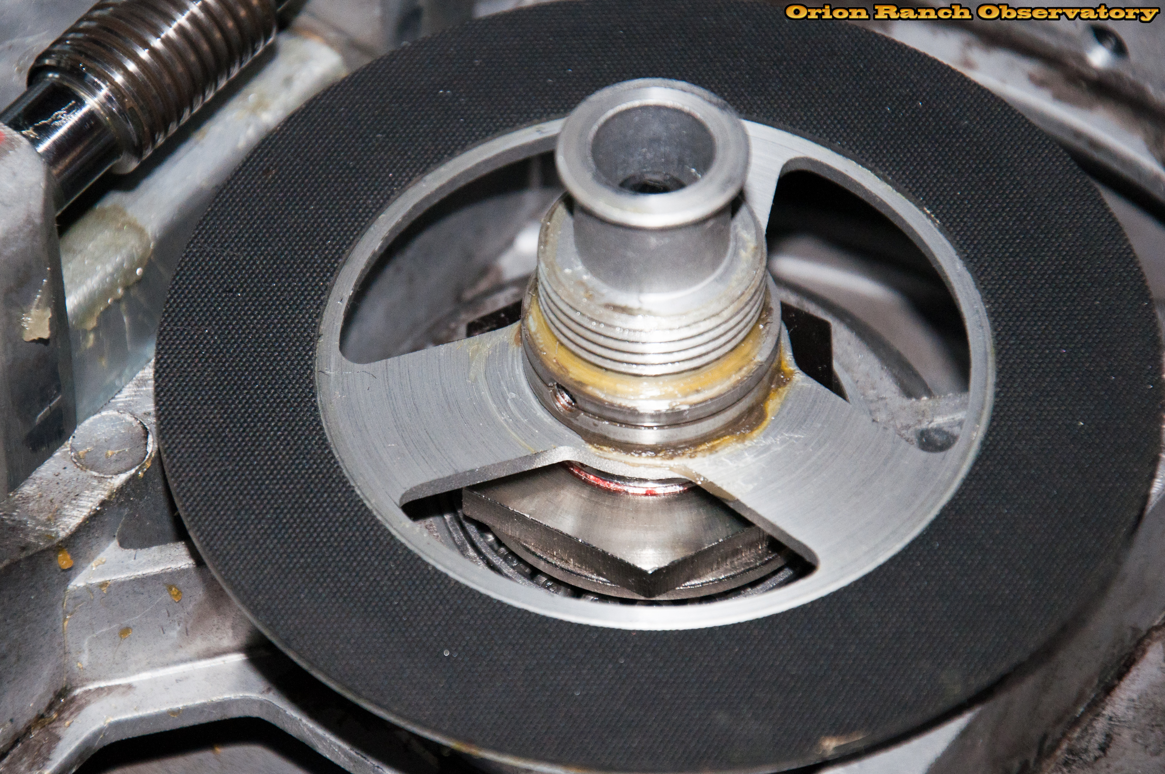
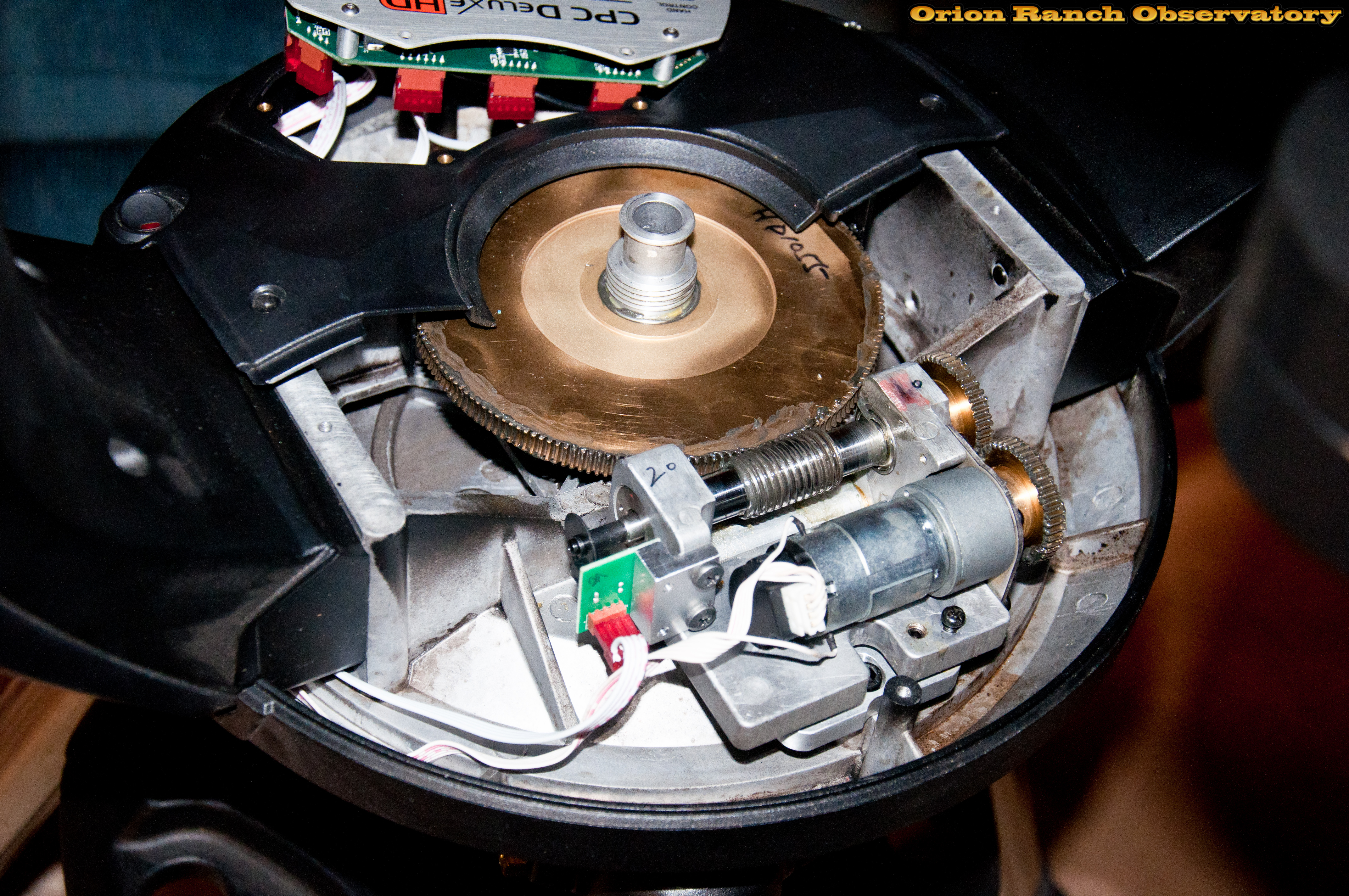
The main gear just slips off the bottom plate. There’s a bit of grease in the middle to let the brass gear slip when the clutch is disengaged. There’s a textured rubber pad on the plate to actually create the clutch grip.
Here’s a close-up of the clutch plate showing the rubber textured sheet, the grease on the hub, and one of the set-screw holes.
Here’s the brass main worm gear and clutch plate after wiping off most of the grease and contamination.
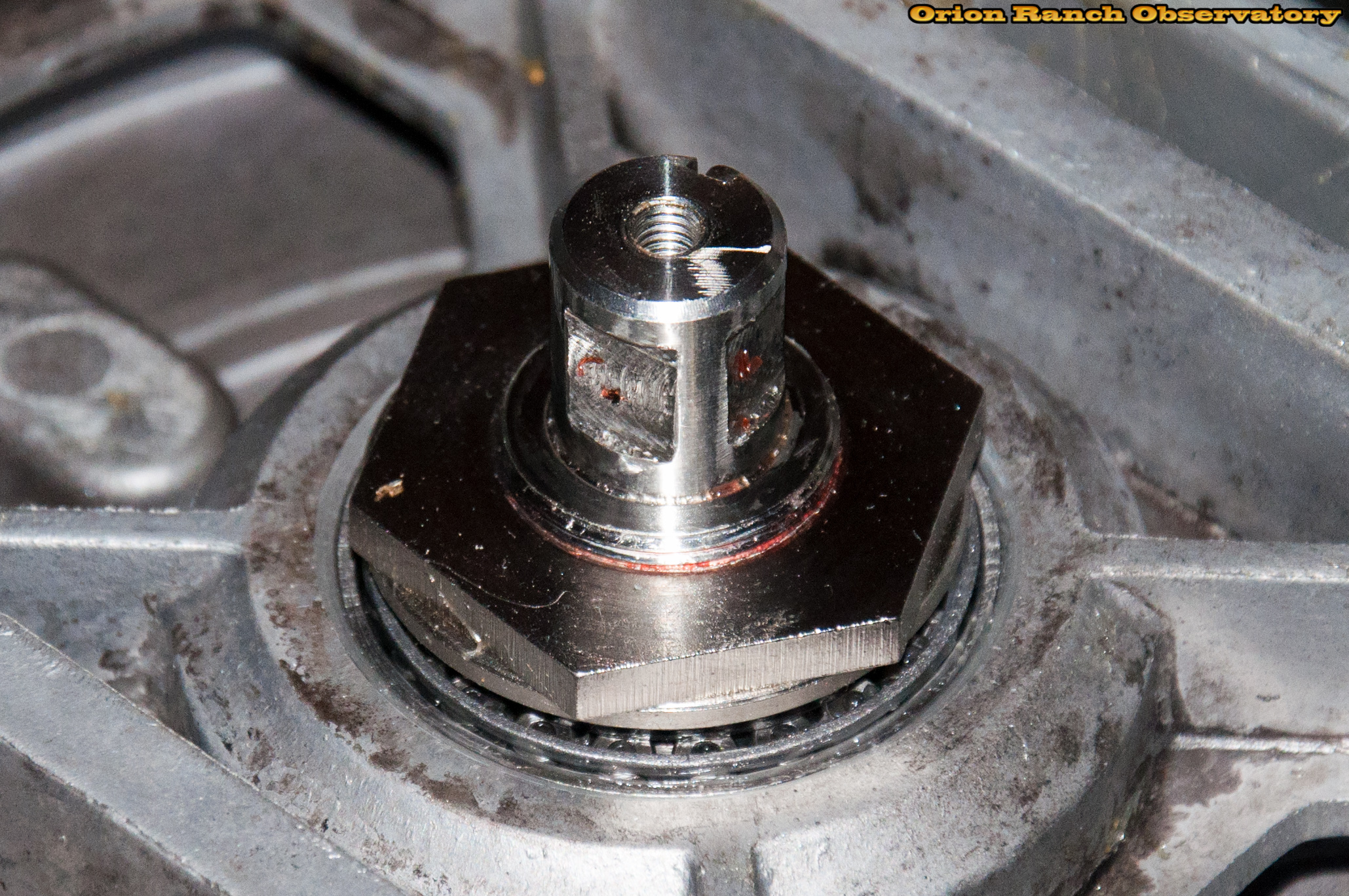
After removing the two set-screws and center screw, the clutch plate will slide off the center spindle of the AZ/RA axis. There are two flats for the setscrews and a key/keyway to keep the clutch plate solidly attached to the spindle, which is embedded in the non-moving aluminum base of the scope.
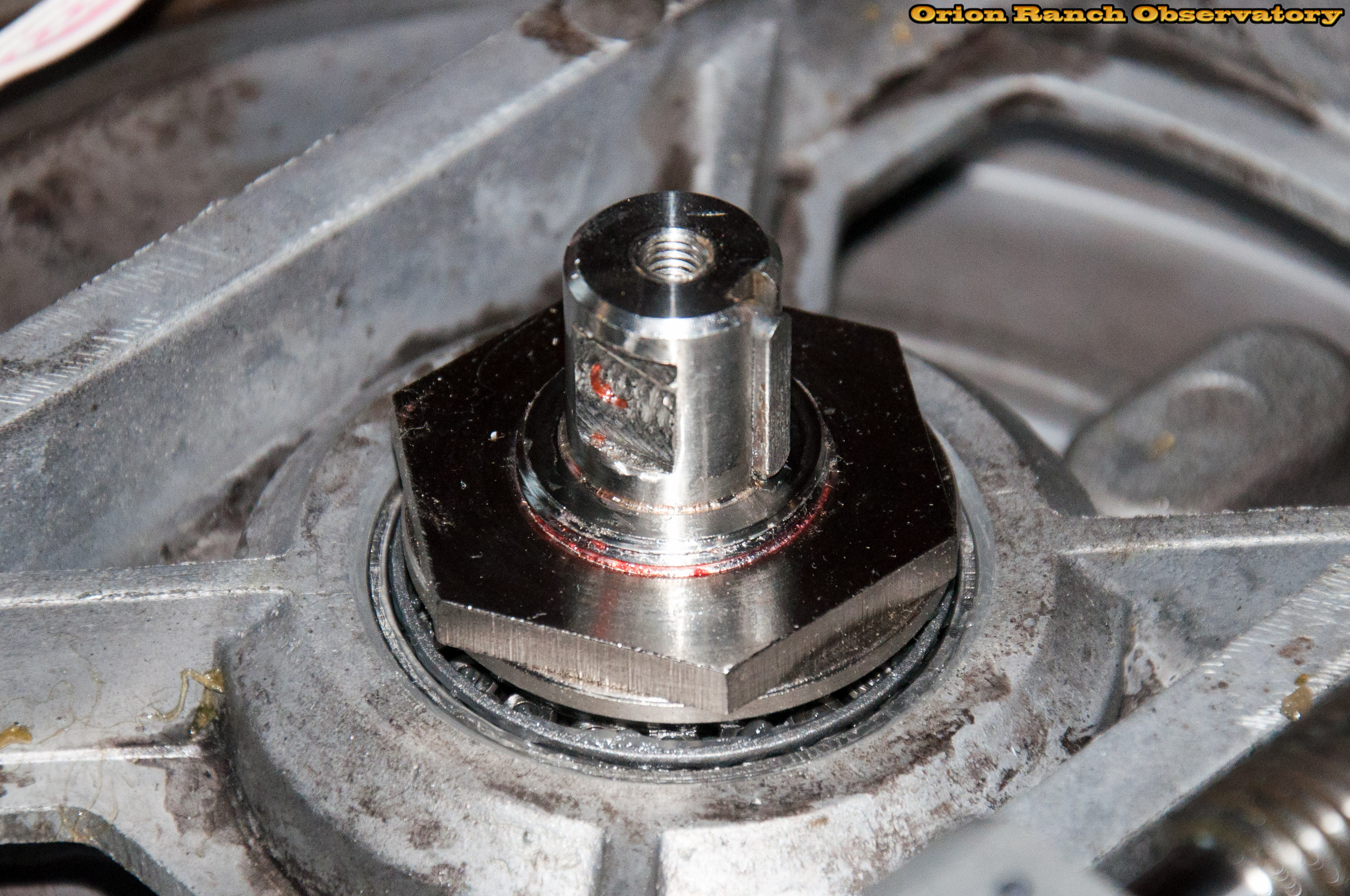
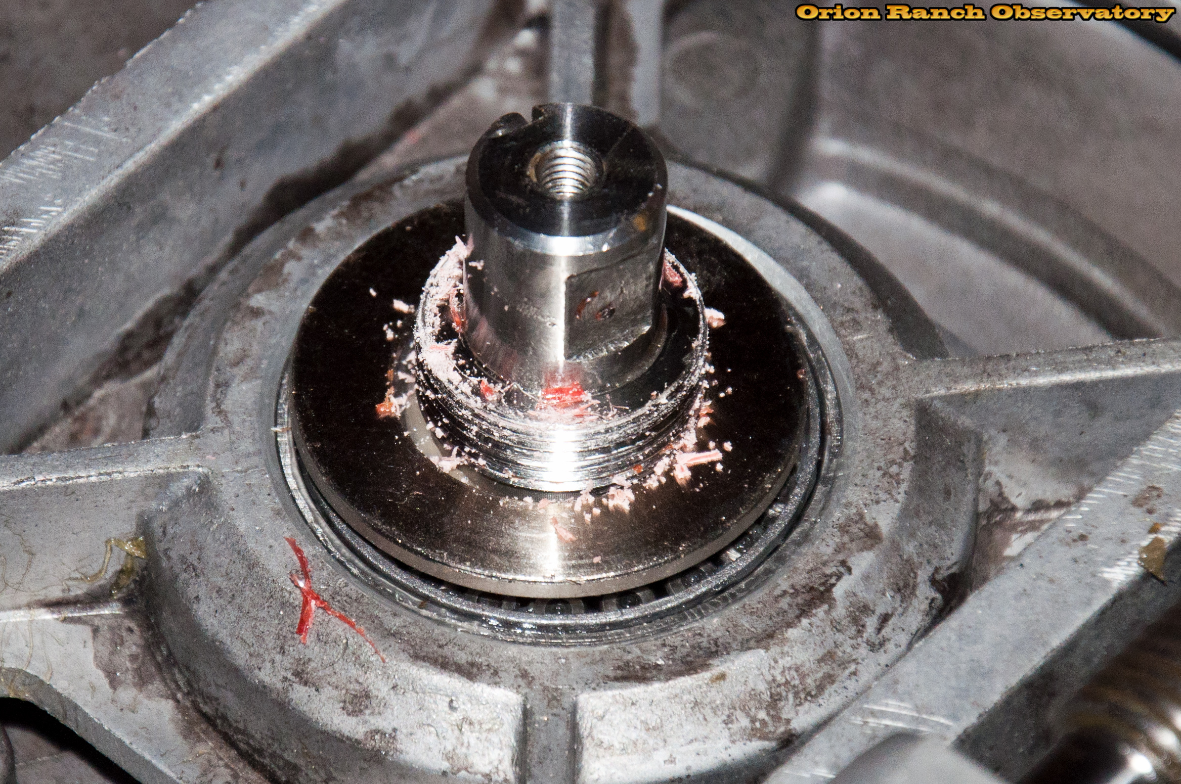
The nut came off the center spindle rather easily, although you can see the remnants of red lock-tite.
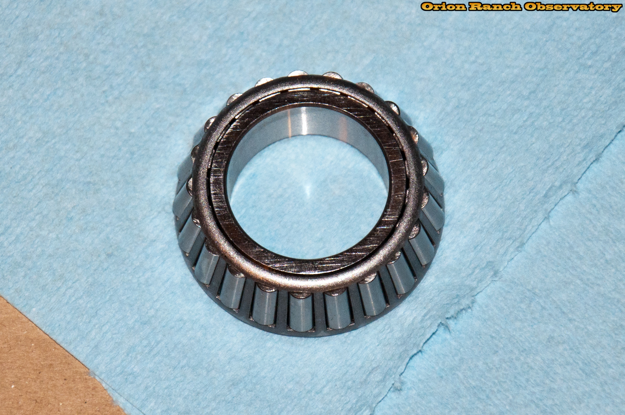
The tapered shaft bearing slipped out easily, freeing the upper assembly.
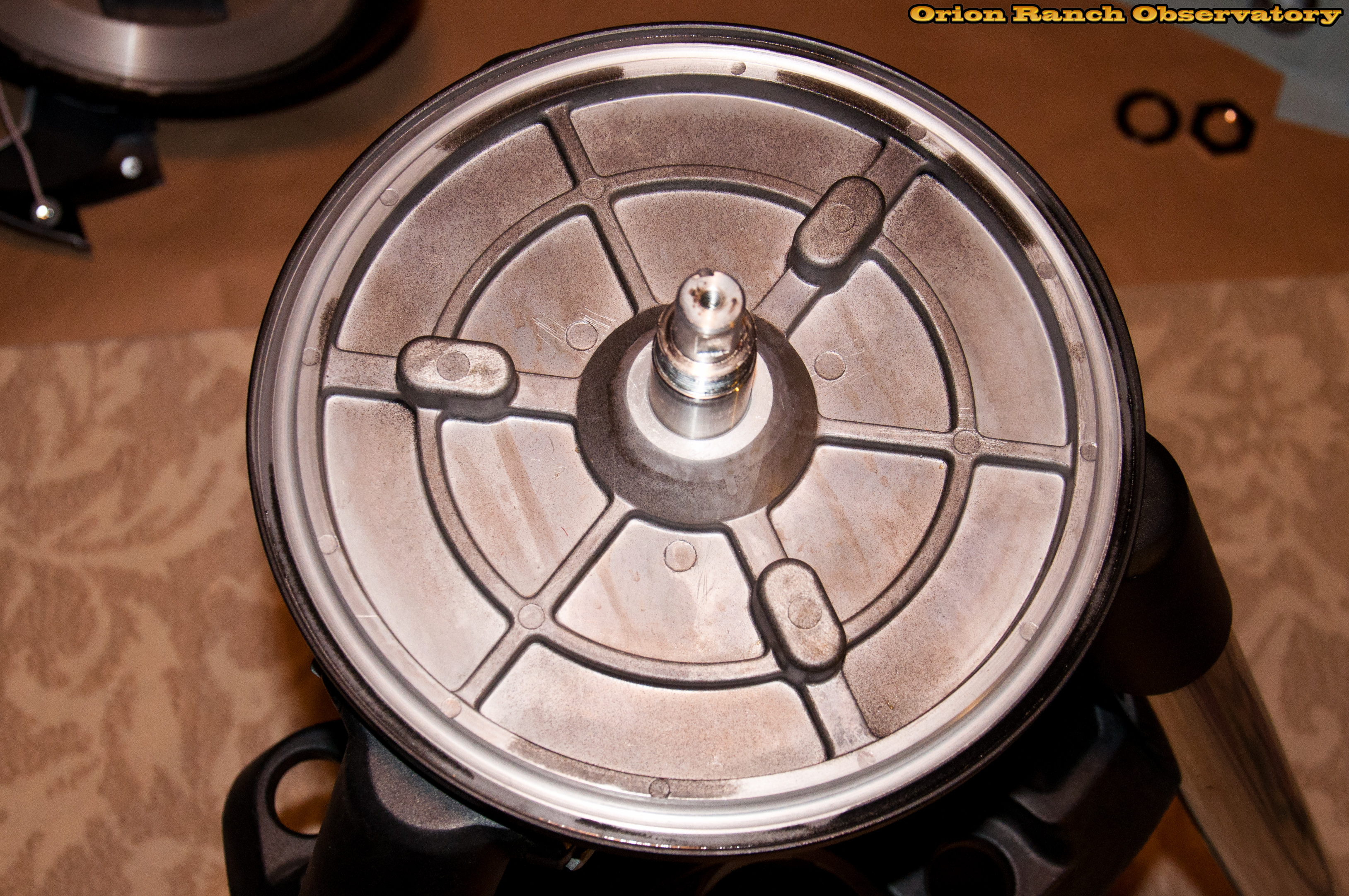
Here you can see the upper assembly after lifting off the base. The portion that rides on the outer bearing is just a flat surface with a taper to the middle. A lip around the edge minimizes dust infiltration.
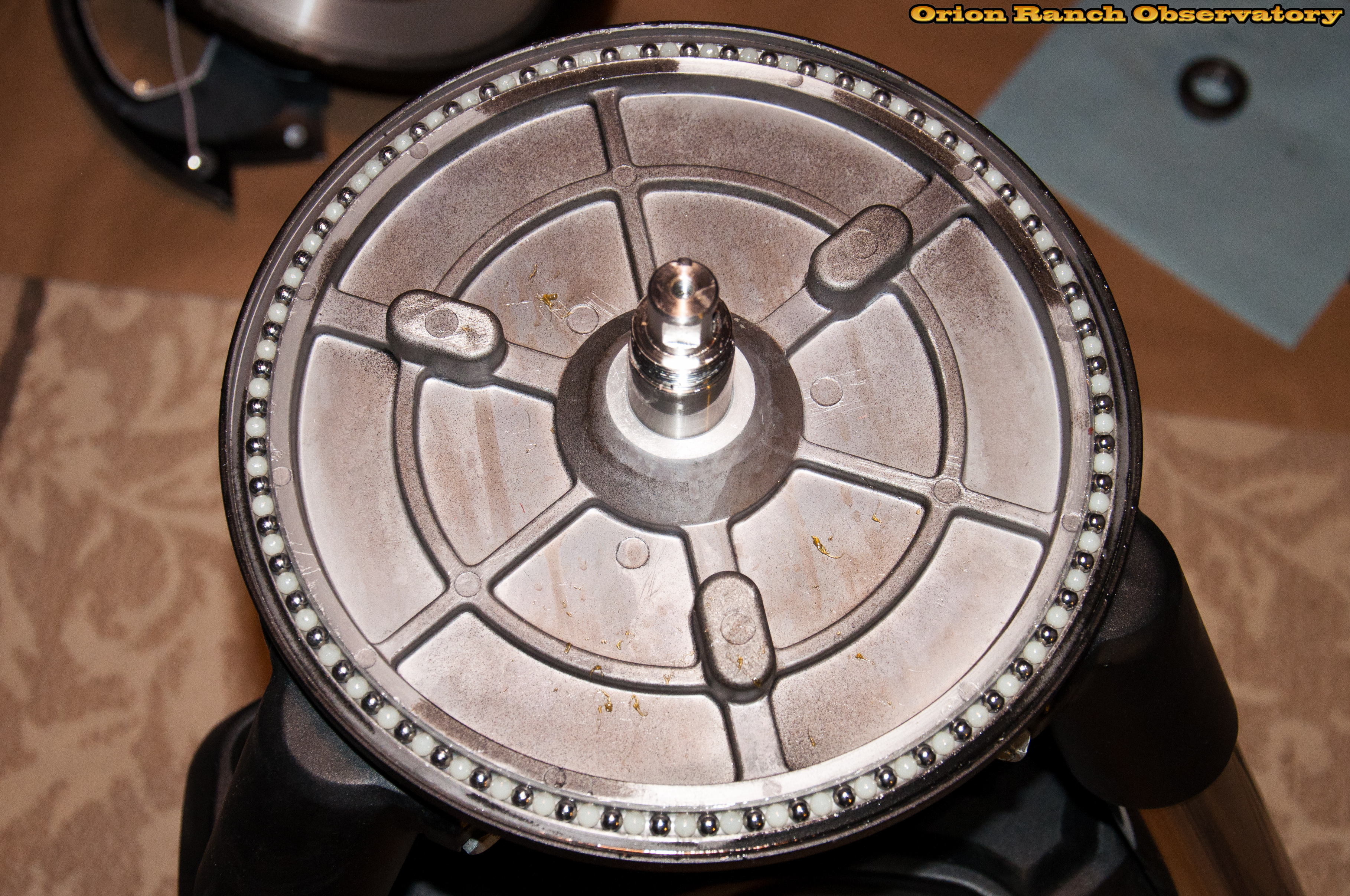
It turns out that the CPC Deluxe HD mount uses a mix of metal and nylon bearings. The balls appeared to be greased in something the consistency of Vaseline. The nylon balls appear to be slightly larger than the metal, but that could be an optical illusion. This mix of metal and nylon appears to work much better than the old approach of using only plastic bearings and after removal of the clutch, the motion was quite smooth and easy. However, by the time I determined that, it made sense to investigate further. By this point, I’m already here so why not try the all-metal approach, saving the existing balls in case I need to put them back.
In the process of removing the bearing balls from the original installation, there were a number of machined metal chips in the bearing and grease that I removed when I cleaned everything up. It’s rather depressing just how dirty the mechanical components were left by Celestron’s manufacturing team.
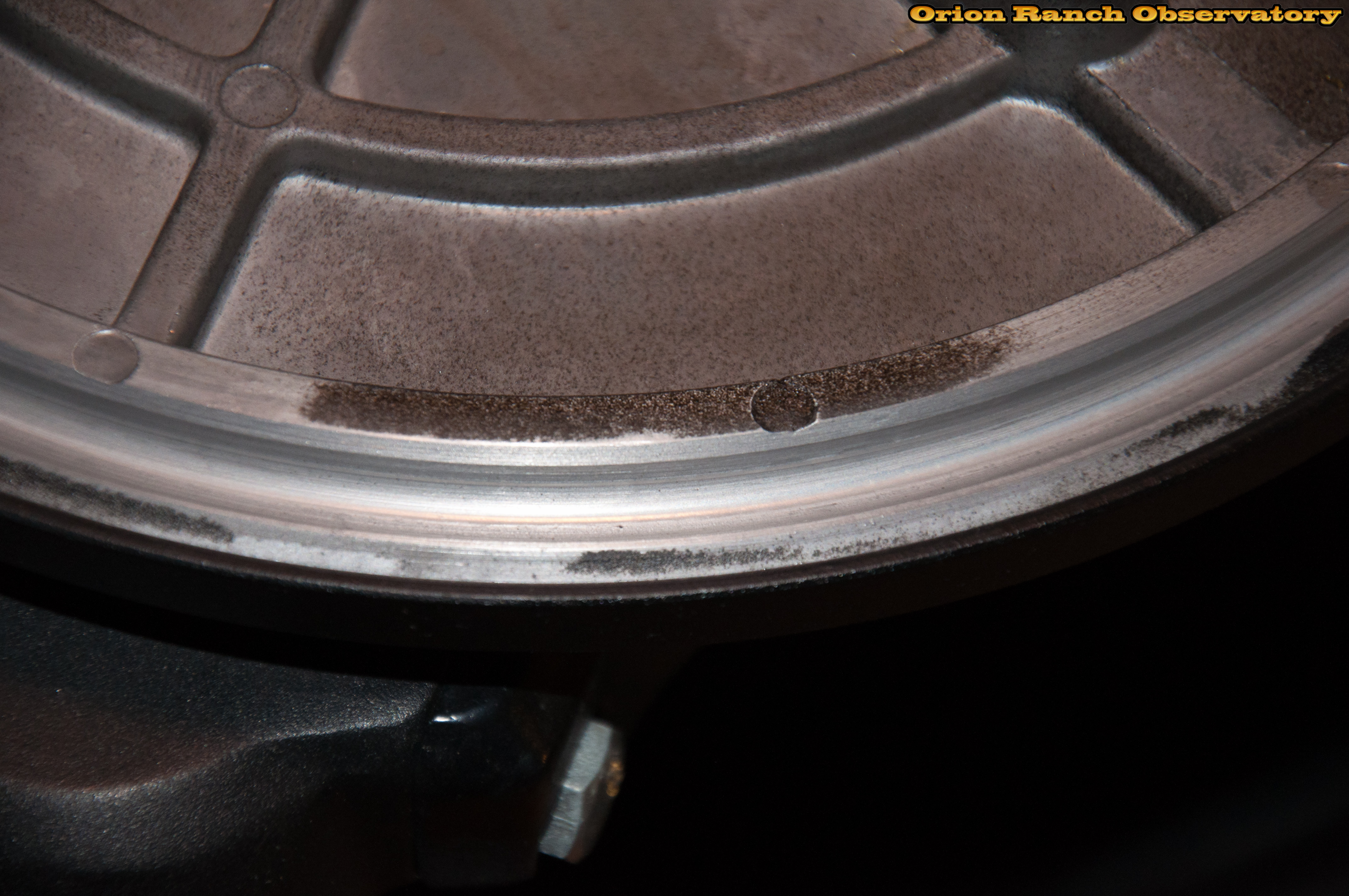
After cleaning the base of both components to remove all old grease (and any metal bits), you can see the bearing channel and lip.
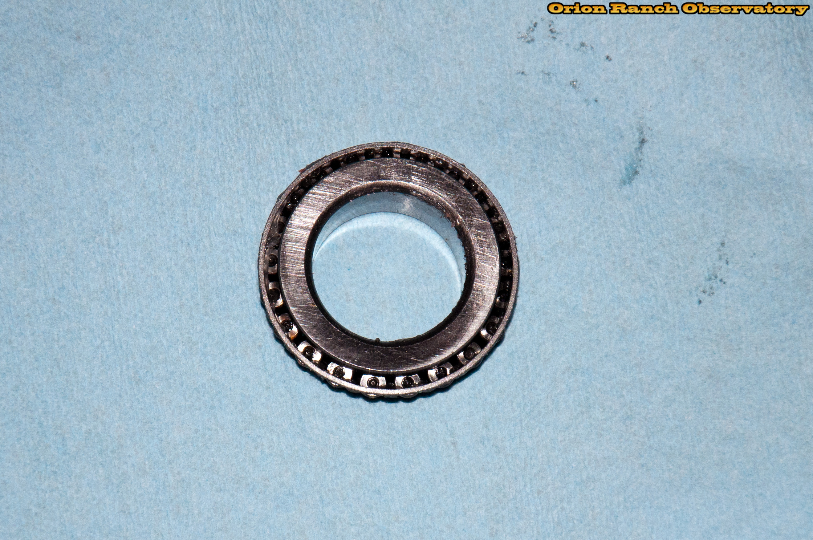
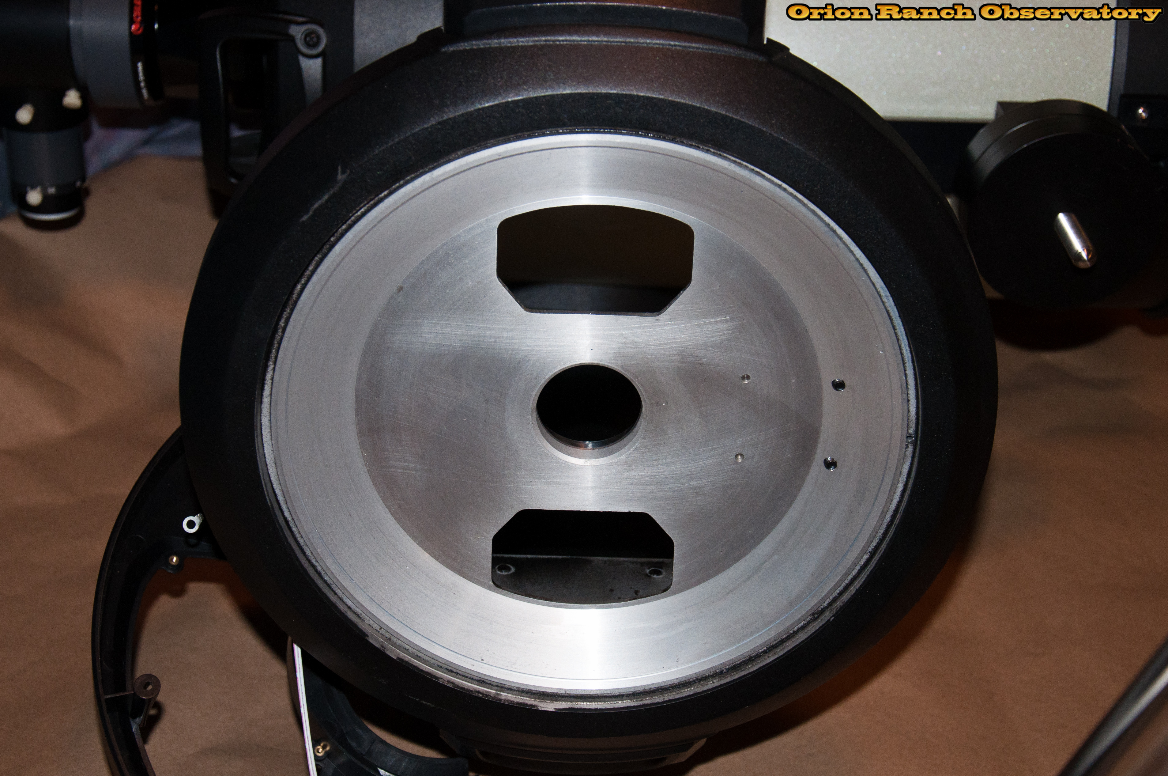
After removing all the grease with a vigorous dip in solvent (paint thinner) the center capture bearing is nice and clean.
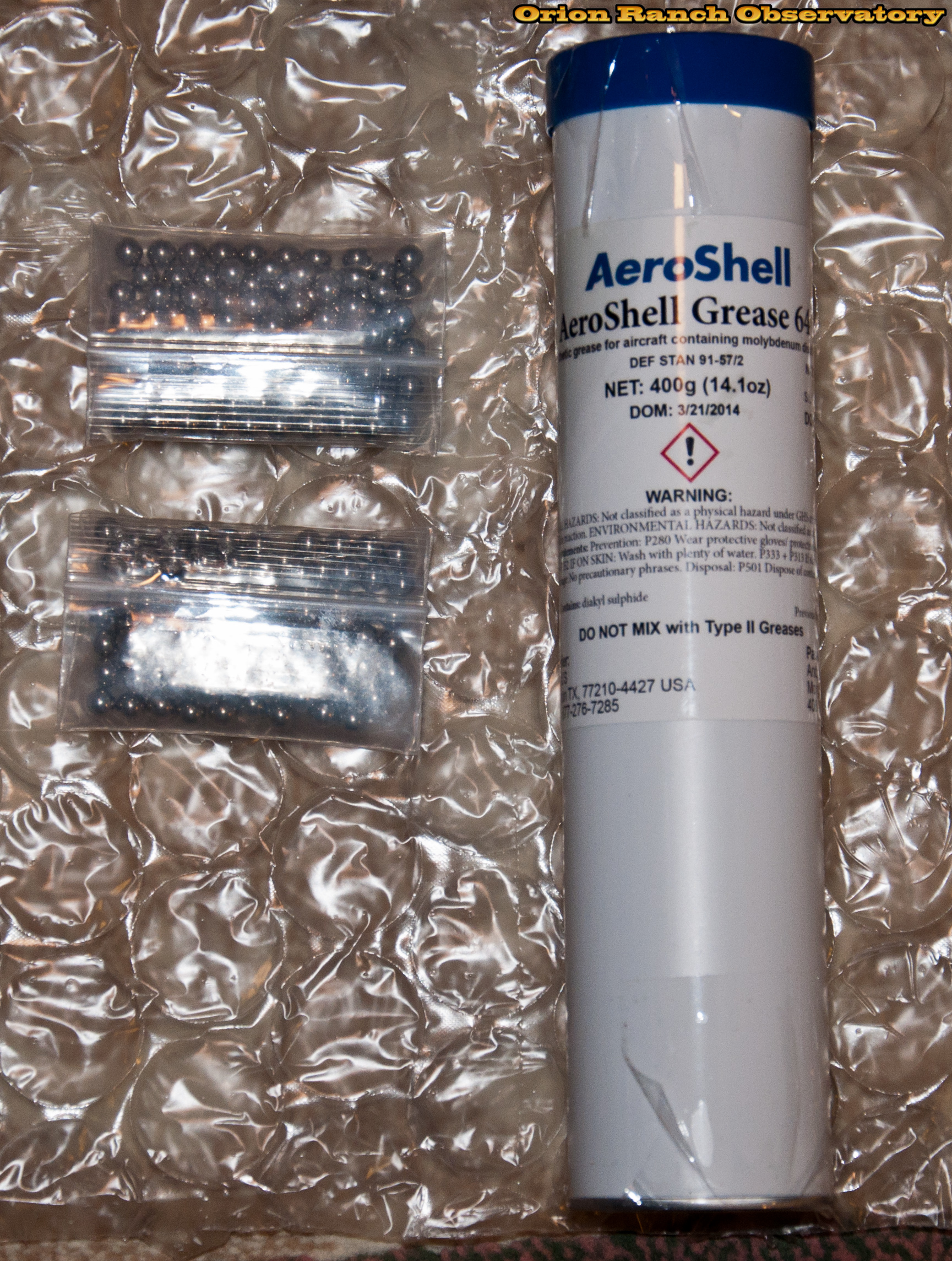
I’m using AeroShell 64 Molybdenum grease, which is a high end aircraft grease with a broad range of operating temperatures and is suitable for high pressure applications. The 1/4″ bearings are stainless steel.
Here’s a picture with all of the 123 stainless steel balls installed with a coating of the moly grease.
Setting the upper body carefully on the base, everything rolls quite nicely, although the all-metal bearings are a bit noisier as the balls rattle against each other. The next step of re-inserting the thrust bearing to capture the unit ended up being the hardest part of the whole process. The tolerance to the center shaft was so tight that the bearing tended to bind with only a mm or so of engagement when not perfectly aligned. This resulted in having to remove the entire assembly multiple times to use the scope to pop of the bound bearing. In the process, the new bearings were upset at least once and had to be re-worked. ARGH! Eventually it went on correctly and I was able to complete assembly. Given the constantly greasy hands, and simple reverse process, it didn’t make a lot of sense to take a bunch of pictures going back.
Finishing up the re-assembly with a shot of the aluminum cover attached to the controller PCB, you can see the four screws that I shouldn’t have removed that attach the panel to the aluminum standoffs.
Here’s a shot of the re-greased main gear and worm assembly after running everything in.
And finally, all closed up, here’s the finished re-assembly of the AZ/RA axis base.
Next up, I still have to rebuild the DEC axis that’s given me more problems in the past. We’re currently in a full moon phase so there’s no point in remounting it anyway, so I haven’t tested it after the alteration (I hesitate to call it an upgrade at this point). More to follow when I get things tested.
As usual, there are more images in the gallery than I embedded here, so if you follow the link icon, you can browse any details you missed.


Pingback: Best Grease for Nexstar / CPC According to Super Lube Expert