December 31st, 2025
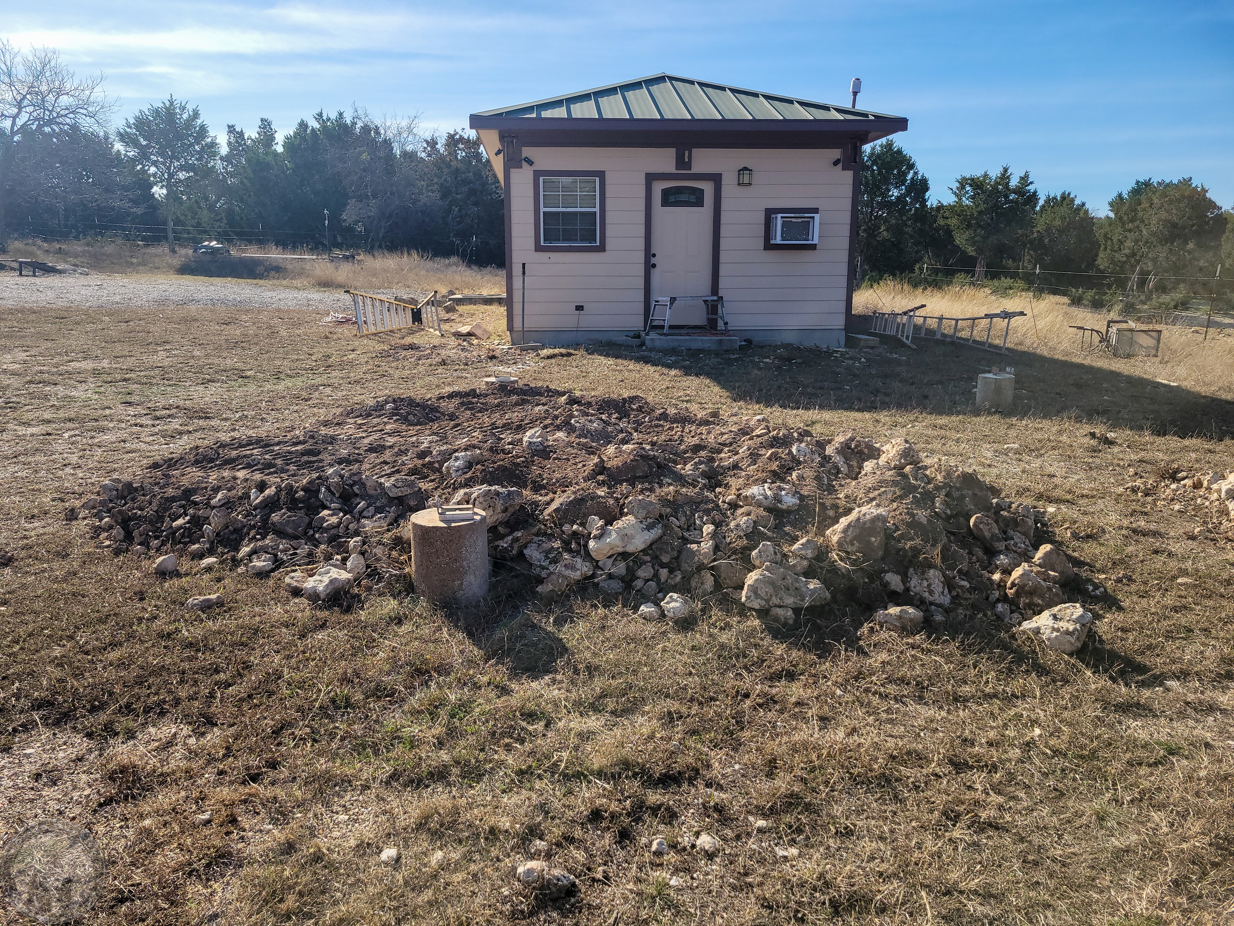
I decided to go ahead and do something I didn’t do previously, which is to level a pad under the rail system. That should make it easier to install each rail using the bucket on the tractor by getting it closer to level. Taking the rails down with the crooked bucket was problematic.
Unfortunately, as my luck would have it, I decided to use my far too big and heavy rock filtering bucket and managed to blow out a hose on the bucket. I won’t get a replacement until mid-week, so I won’t be able to finish the pad until next weekend. Hopefully I can at least make some progress with posts tomorrow.
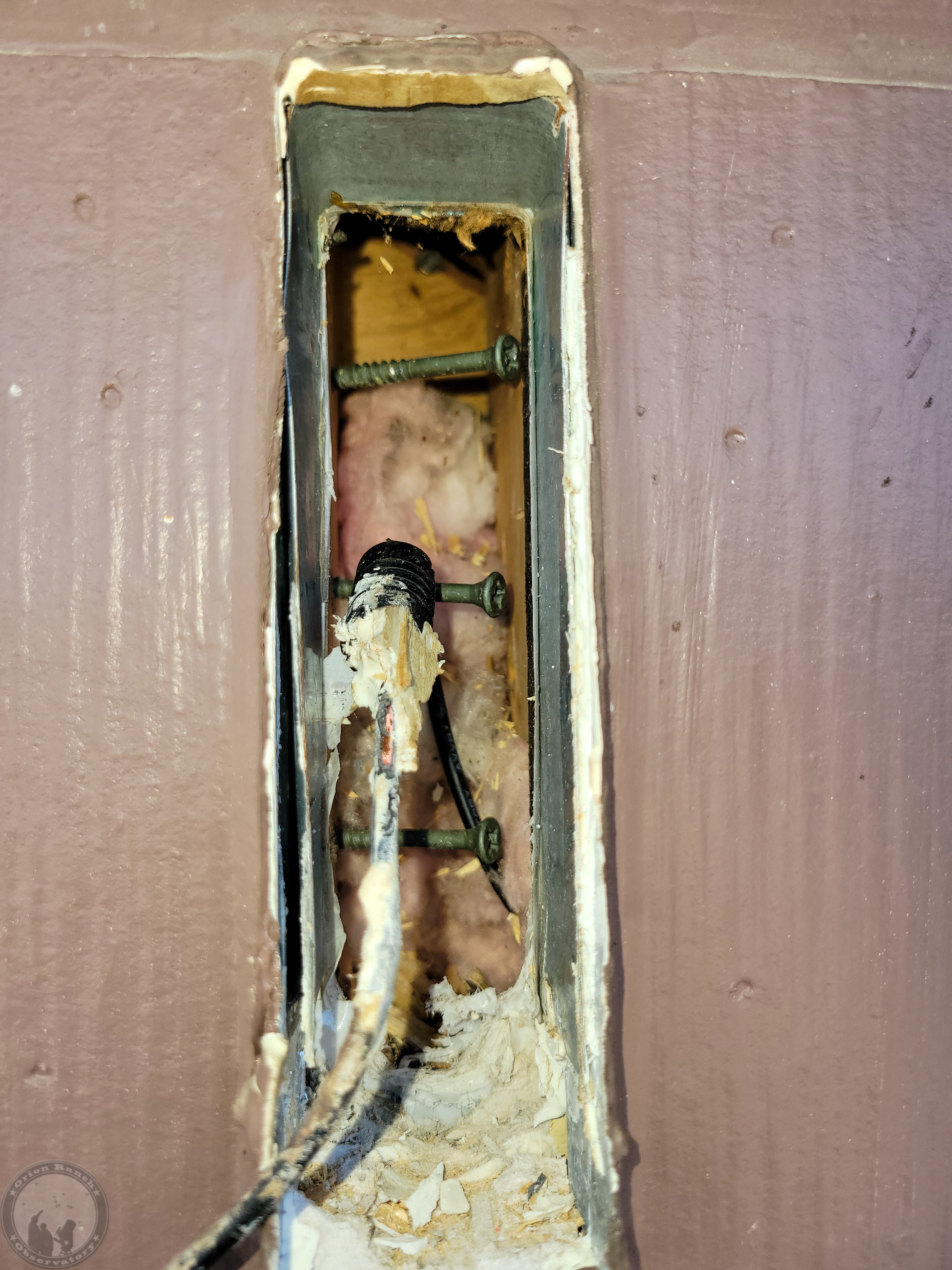
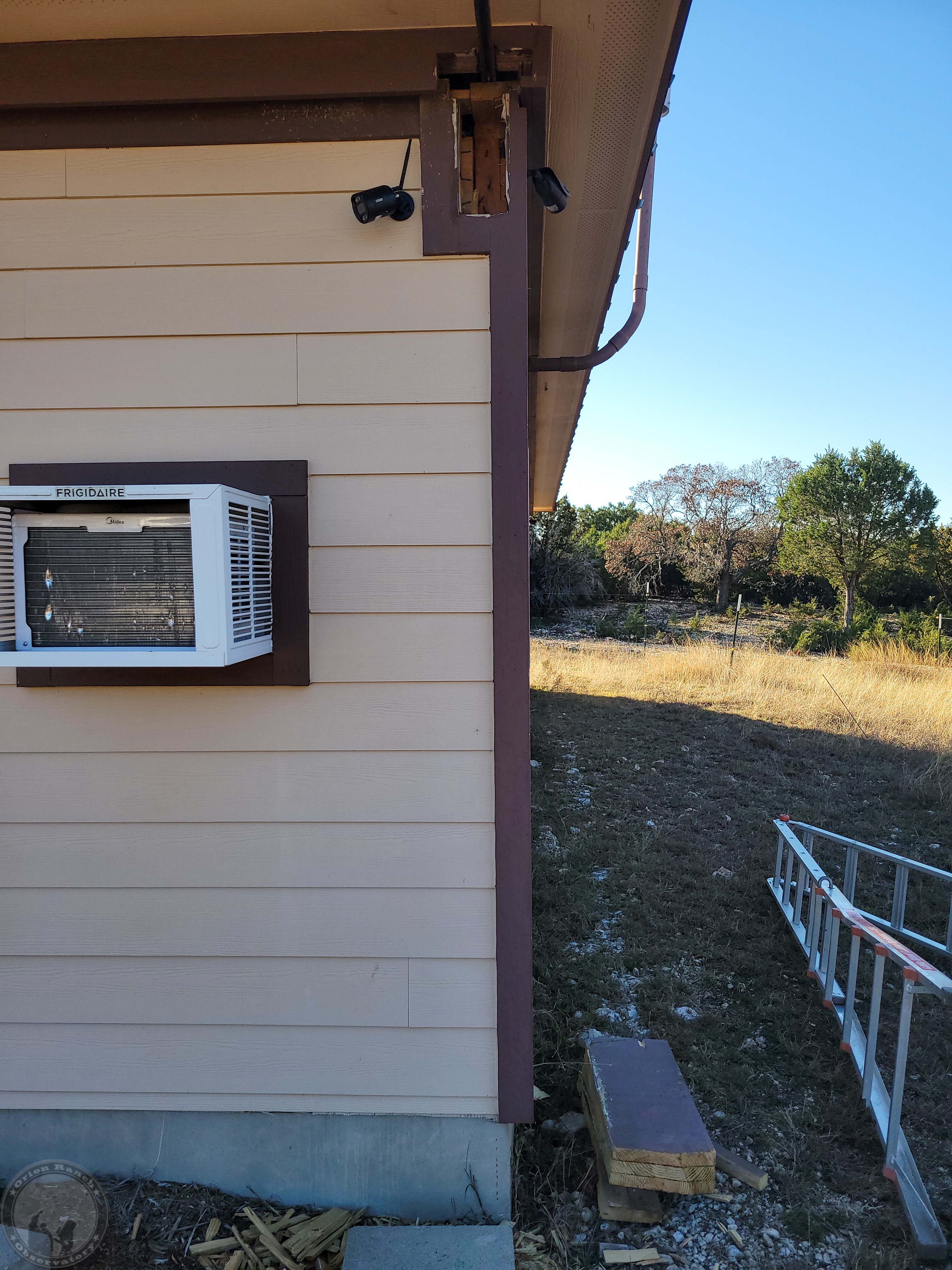
I did at least get the middle brace out as well. It wasn’t very deep into the wall.
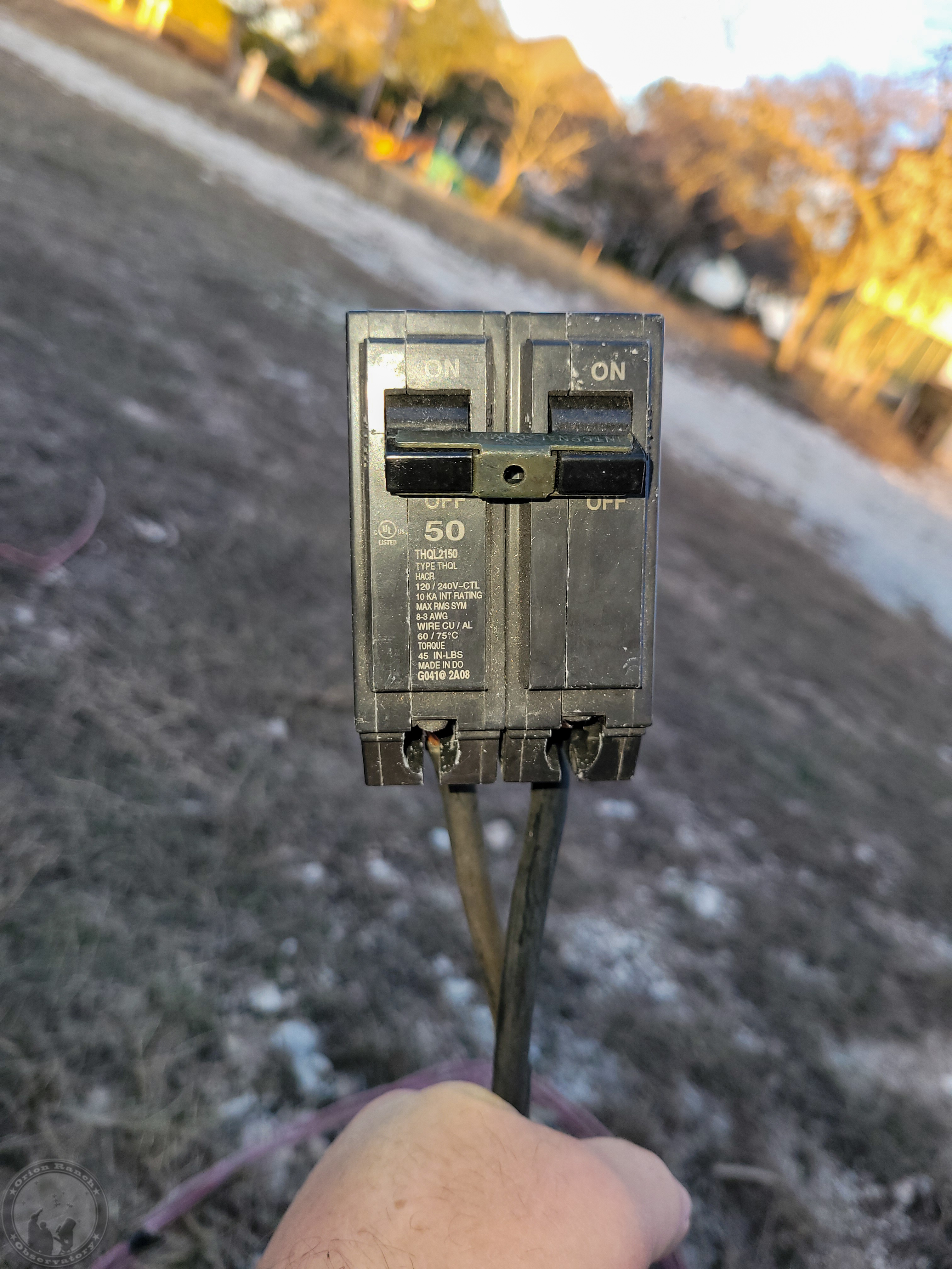
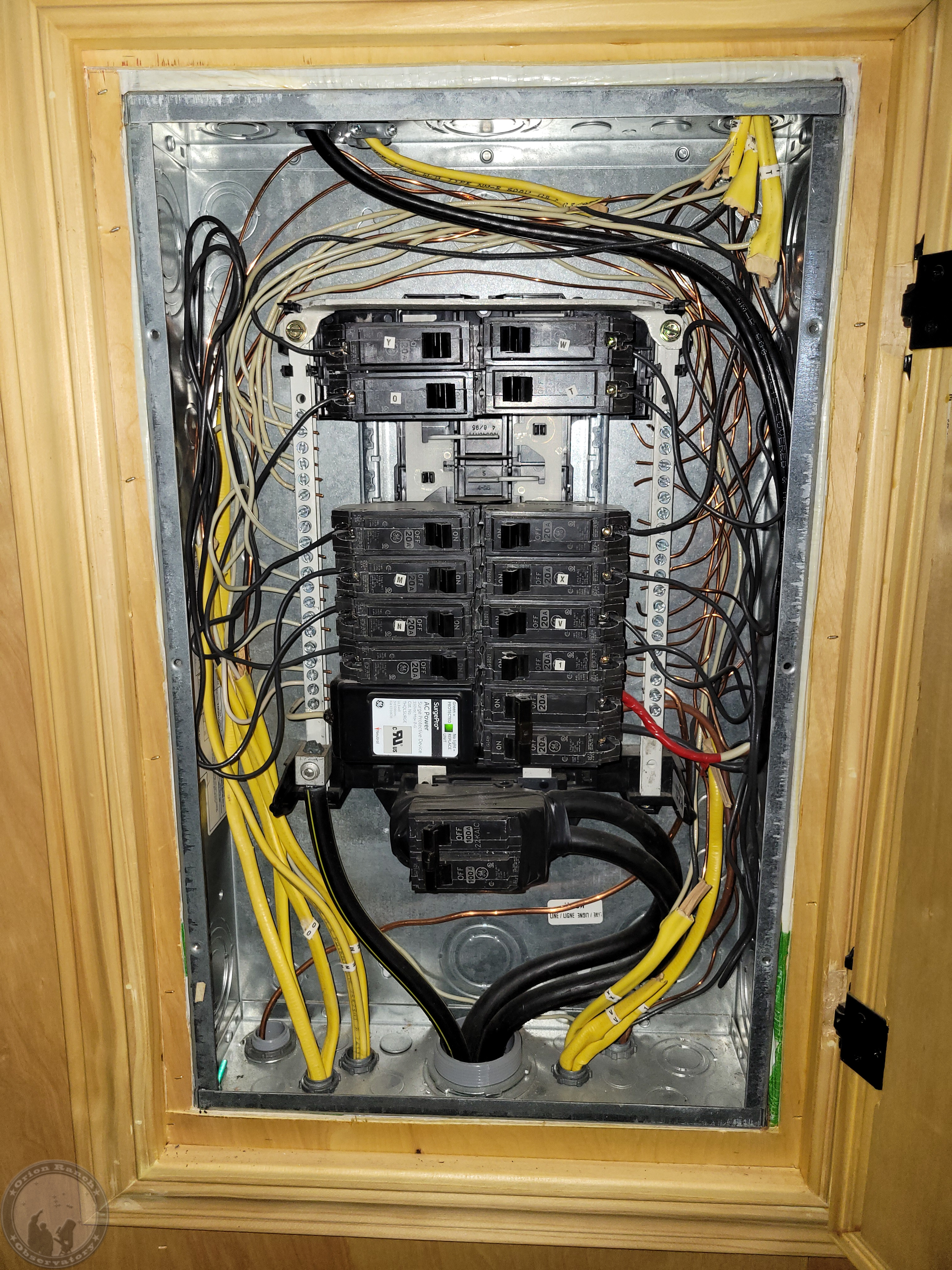
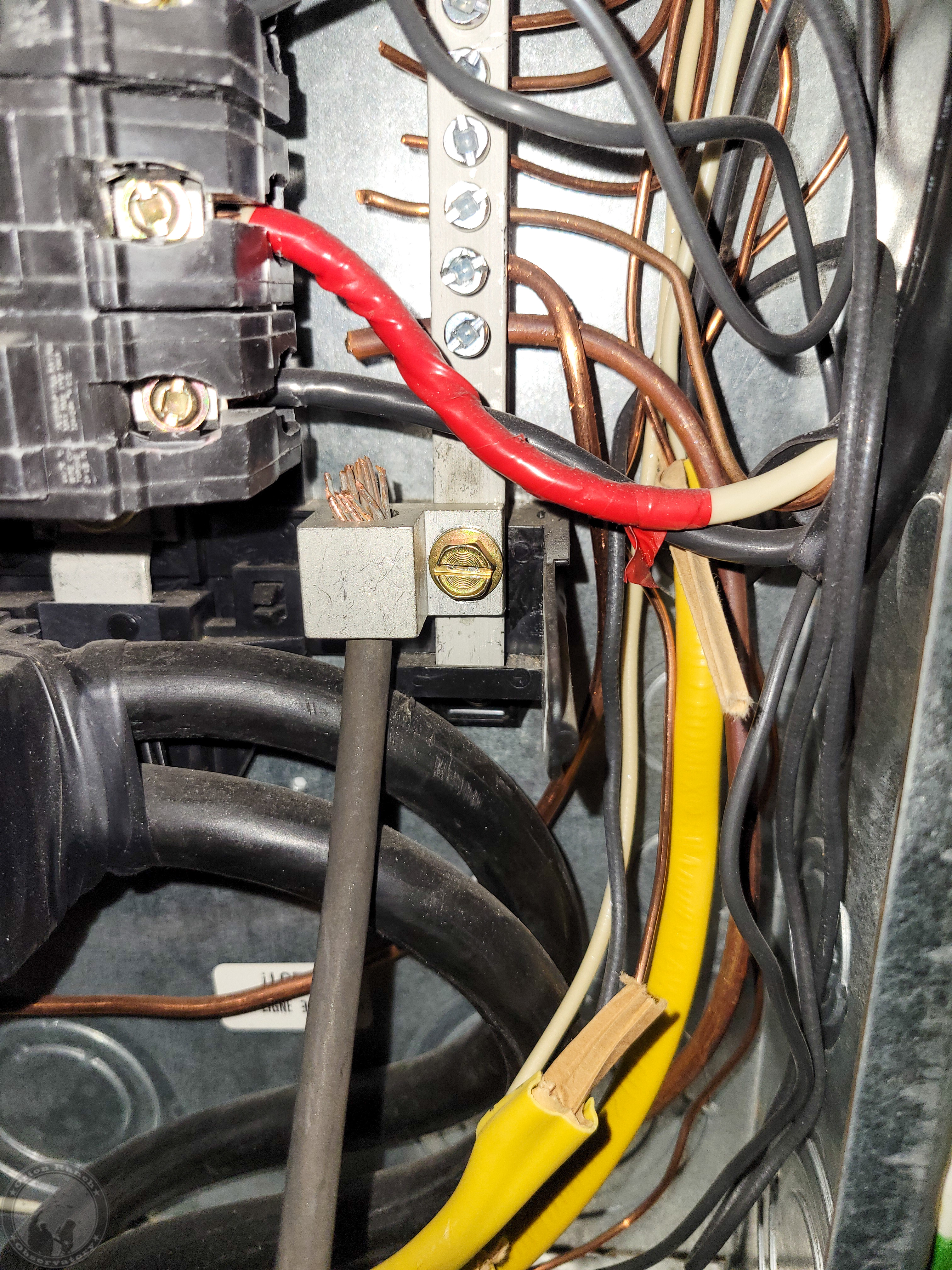
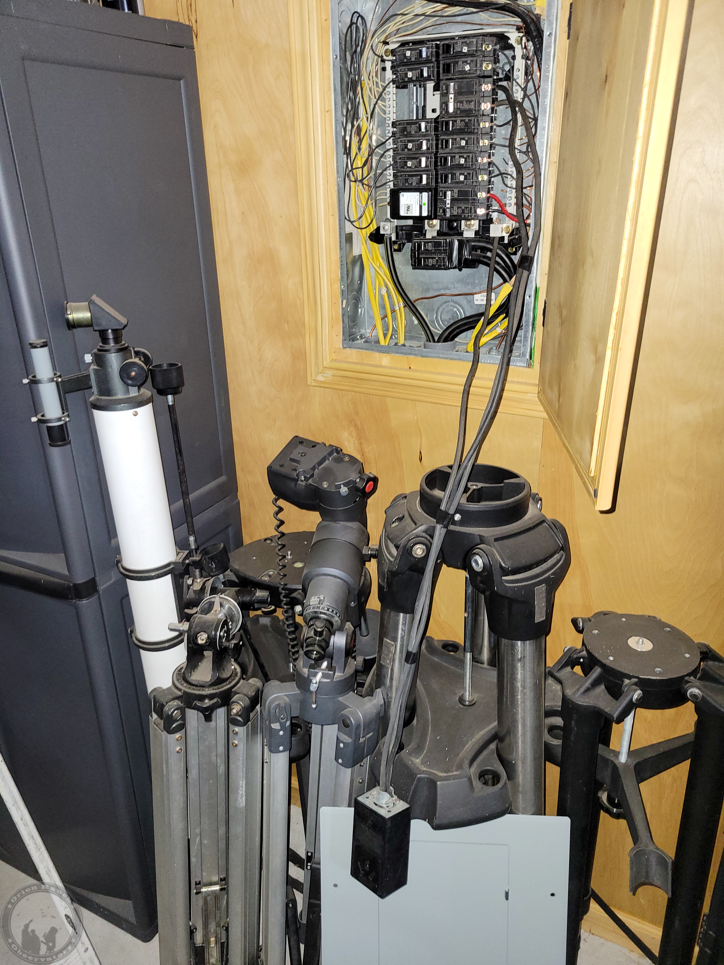
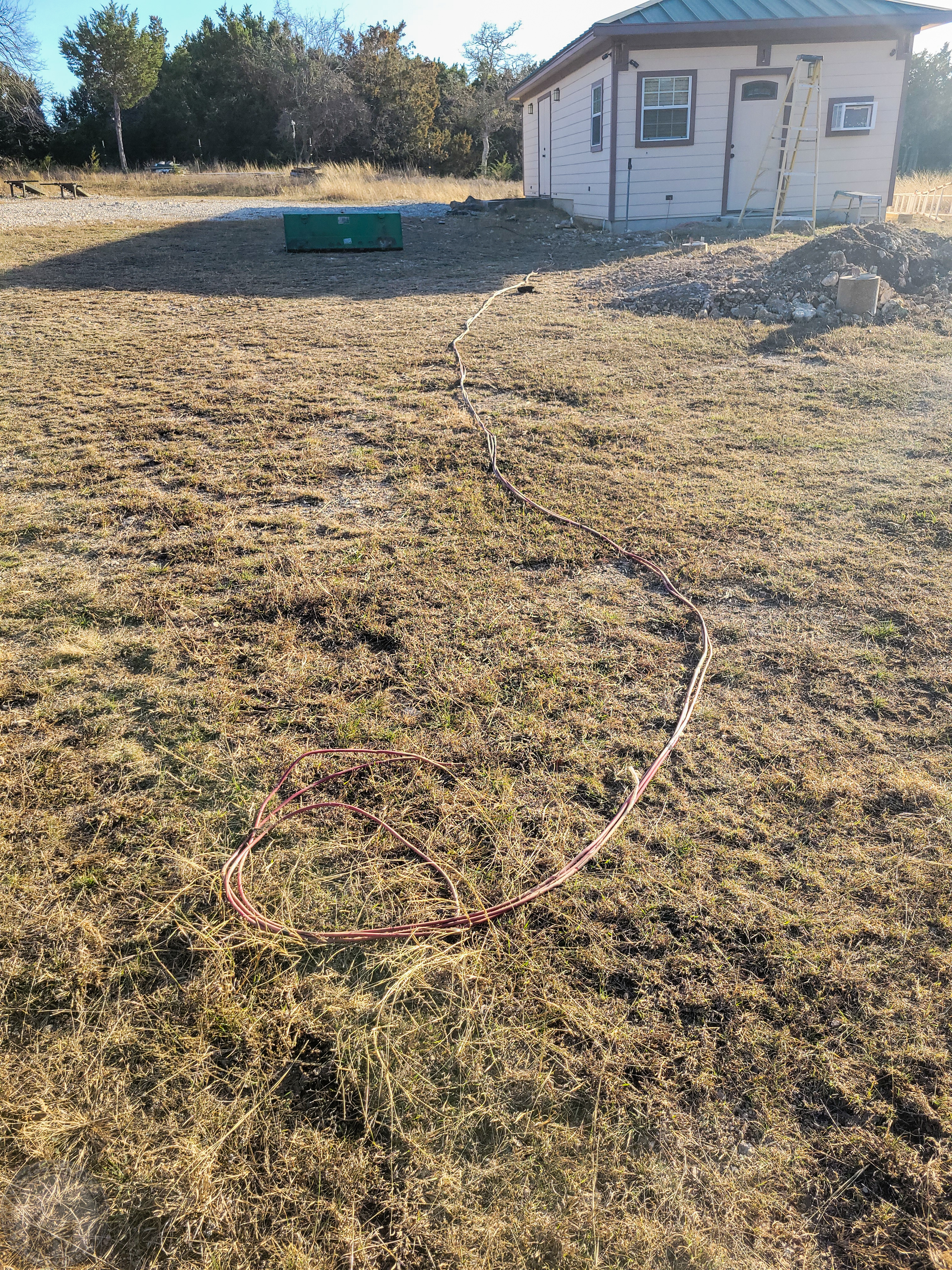
I also got the temporary power installed for running the welder. I still need to finish putting together the extension cable I’ll be using based on the 2 AWG wire that used to feed the old shack out there instead of using a few 6 AWG extensions. With the 2 AWG, it will be just like being plugged in directly. I’ll finish the extension tomorrow.
January 3rd, 2026
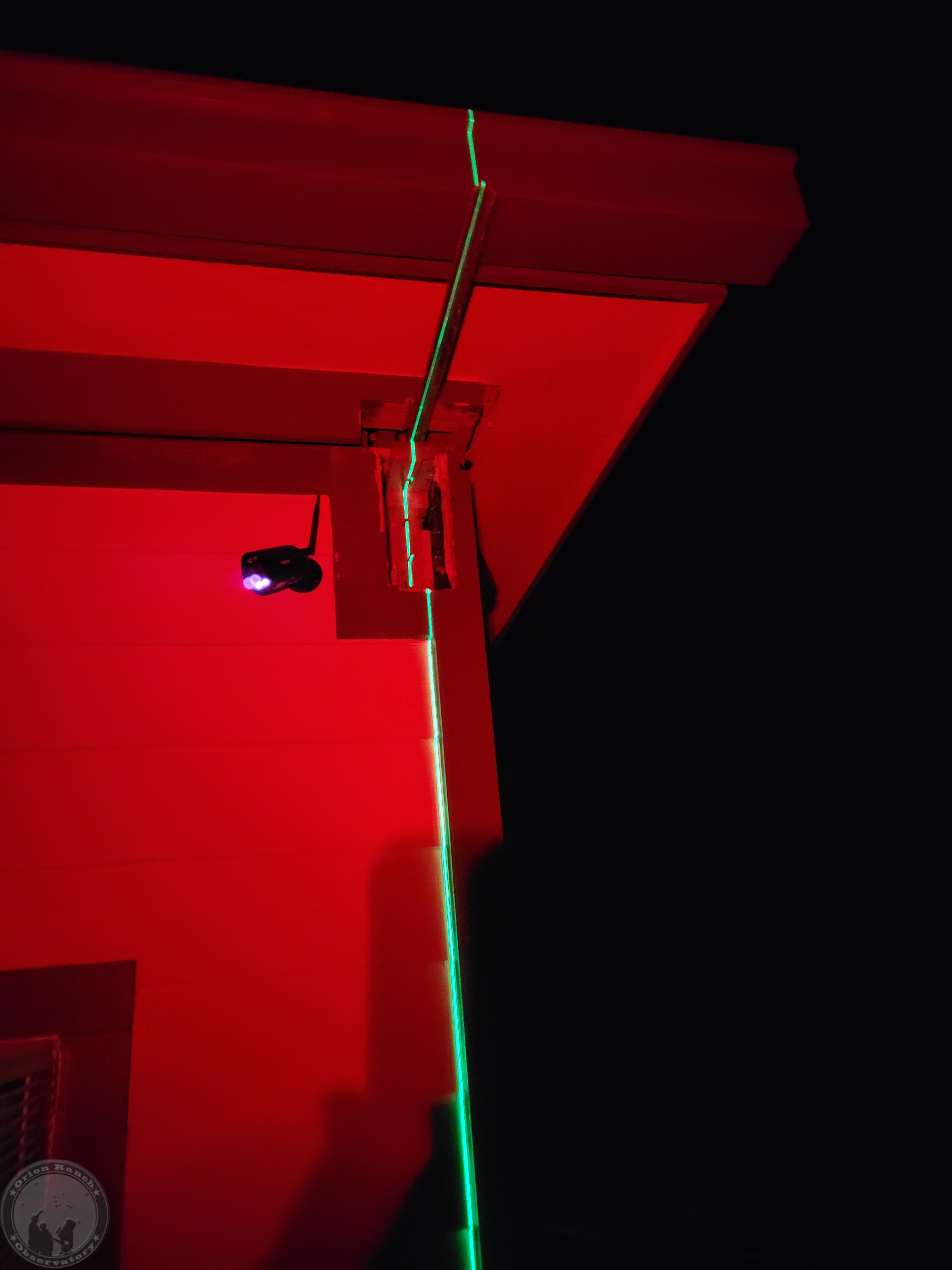
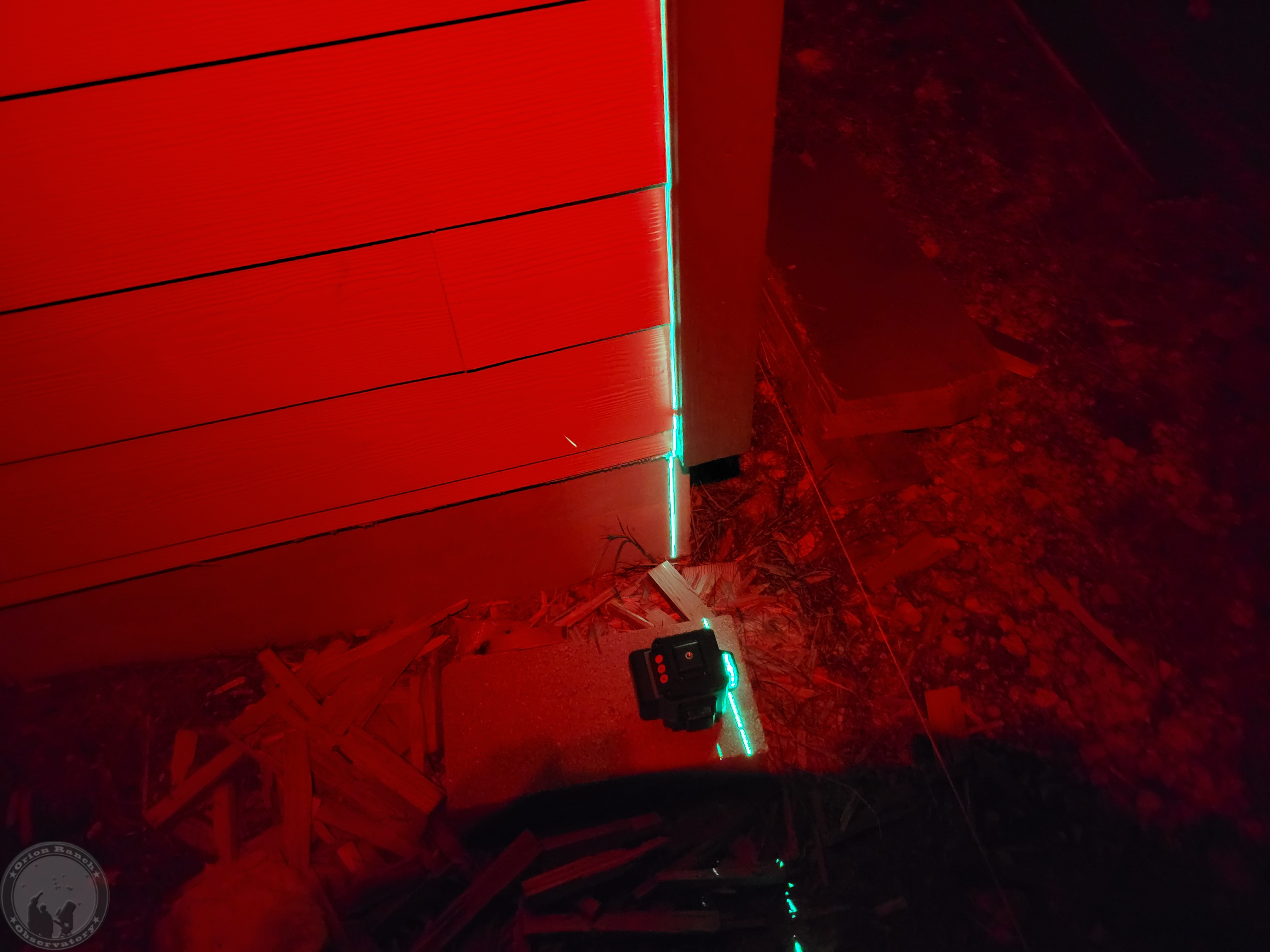
I made a bit more progress, although never as much as I hope! I started by getting out my self-leveling three-beam laser and attempting to transfer the centerline of the angle iron to the ground. Tough to do with the Sun up, but still not everything I need to ensure things are perfectly aligned.
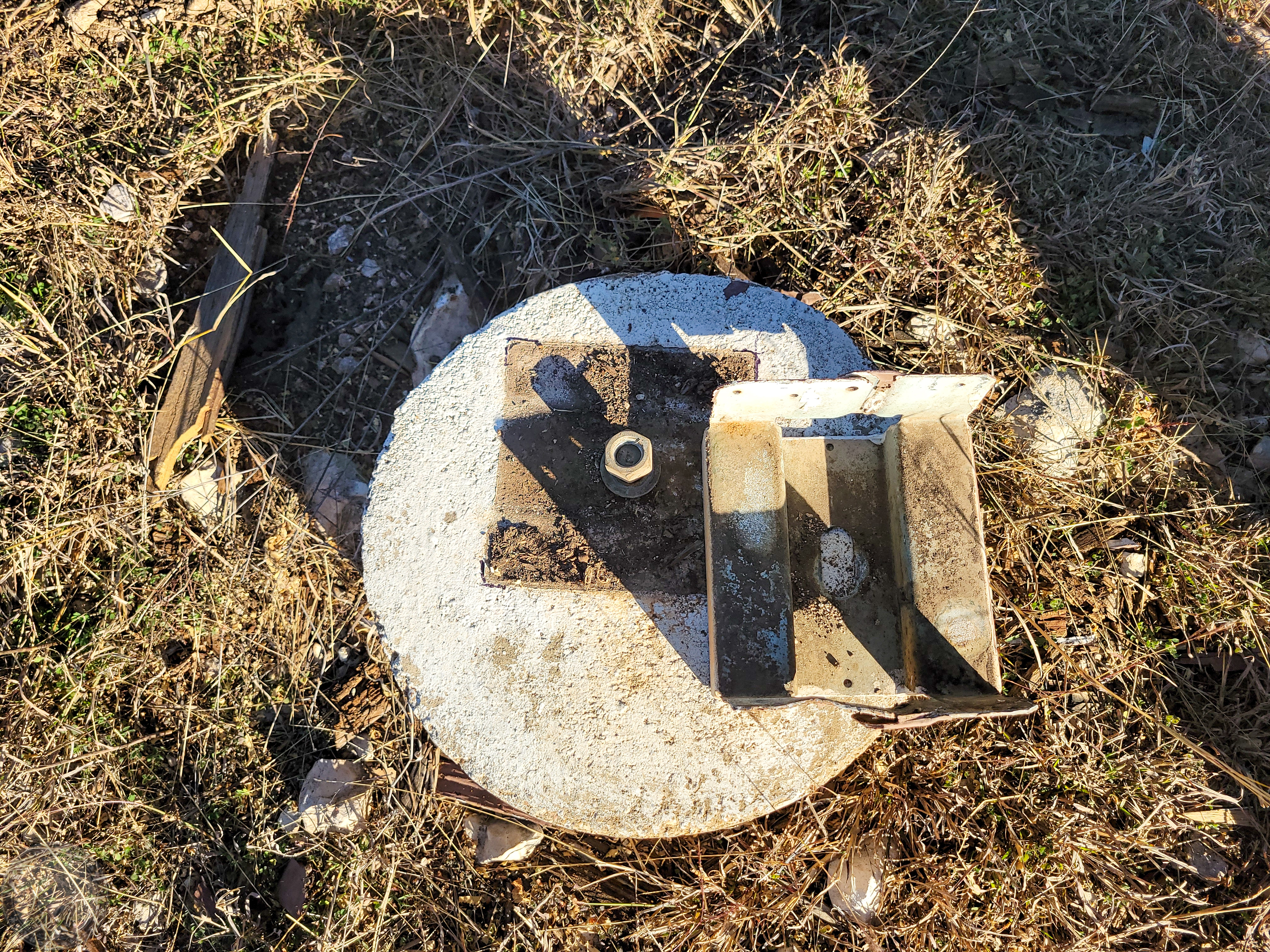
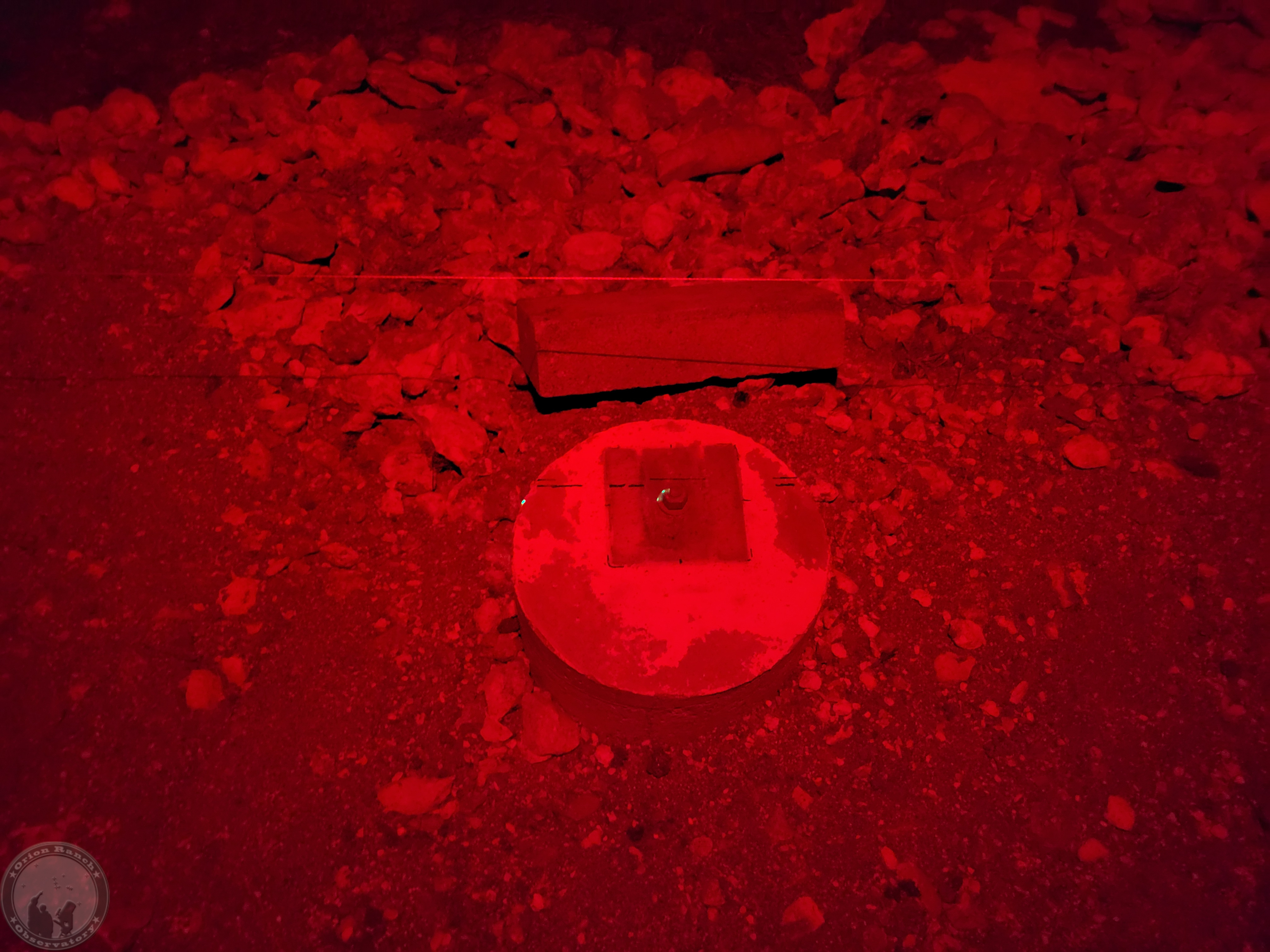
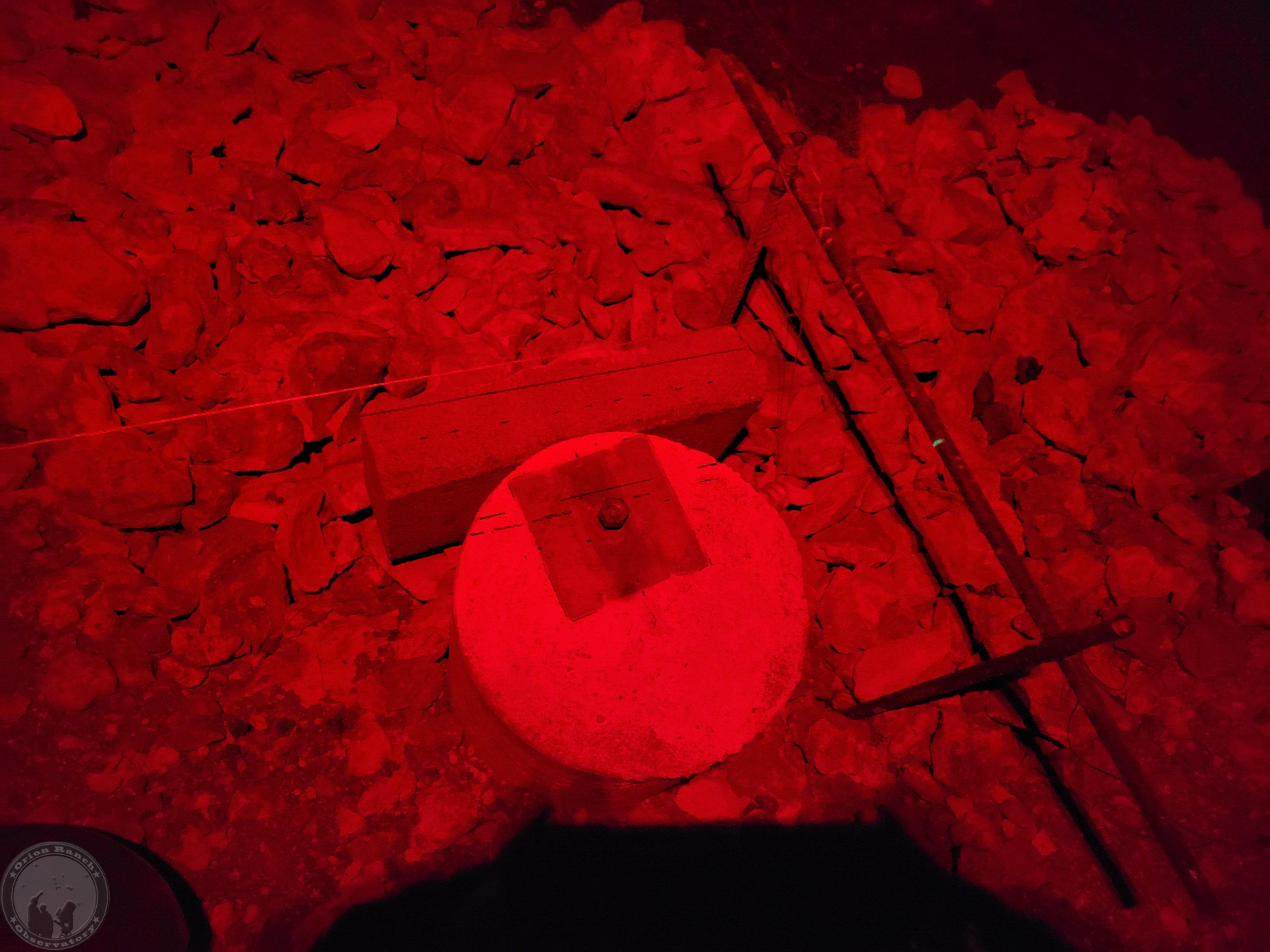
I then proceeded to remove the post bases and run strings to determine how well those center studs aligned with my mark. Looks like things are within half an inch. I’ll try a few other steps before I lock anything down completely.
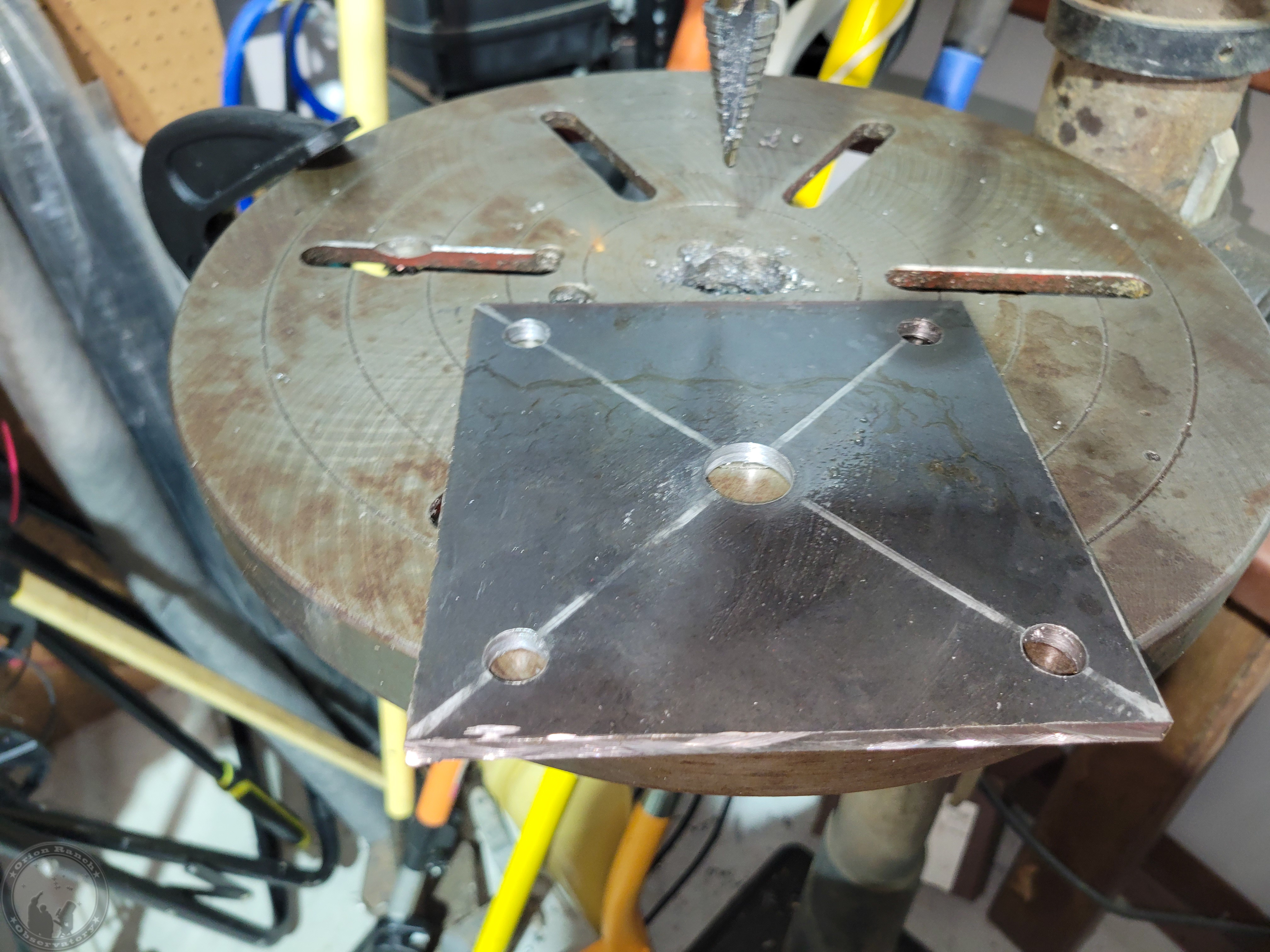
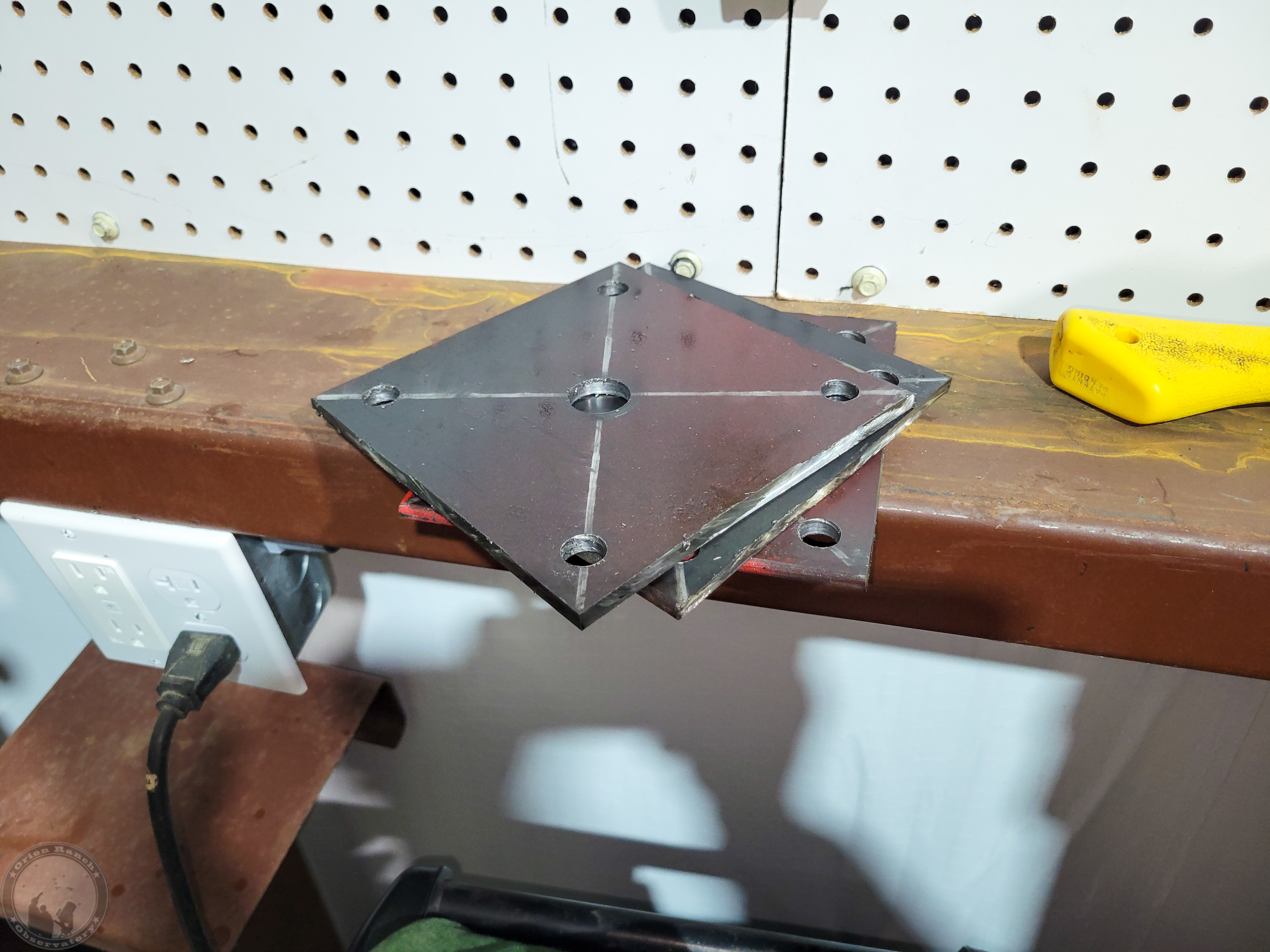
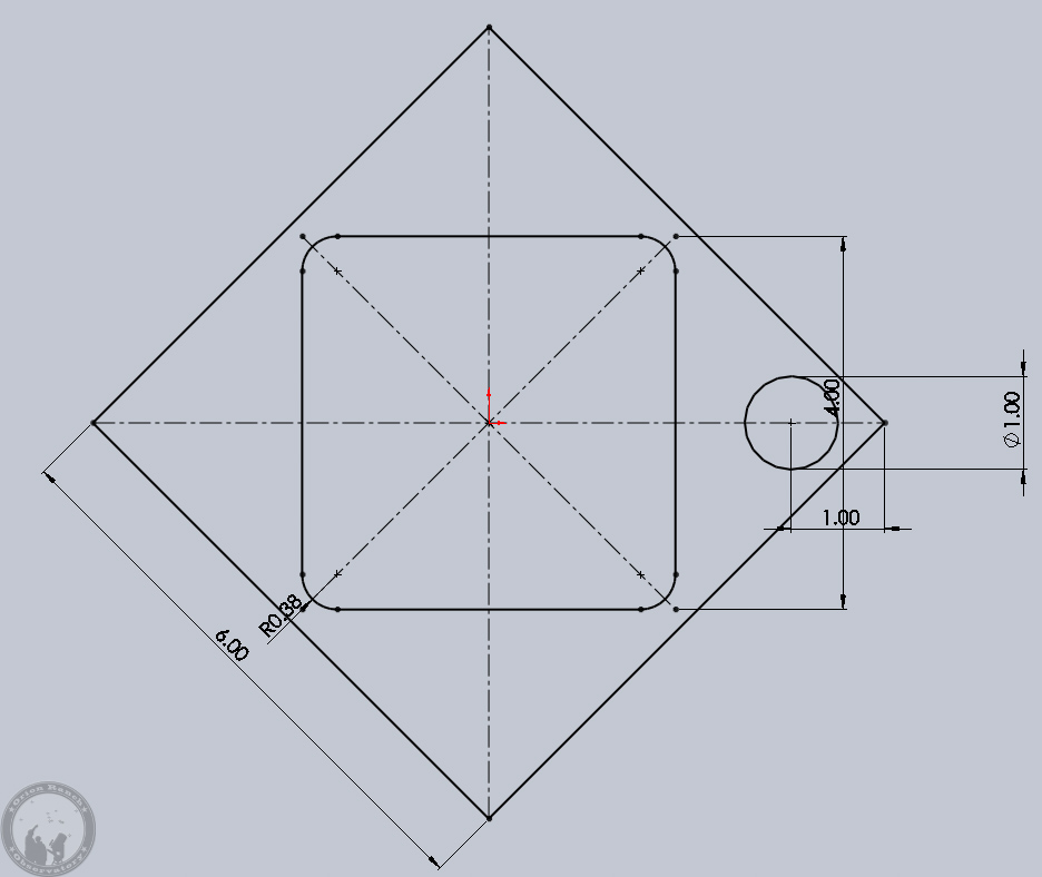
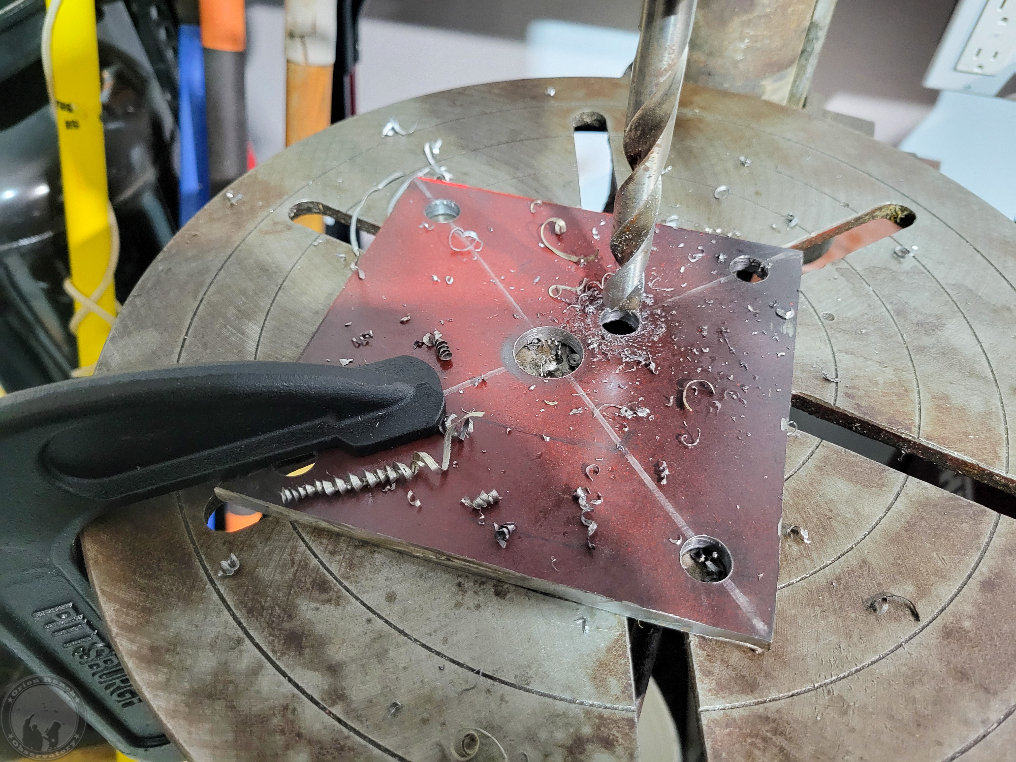
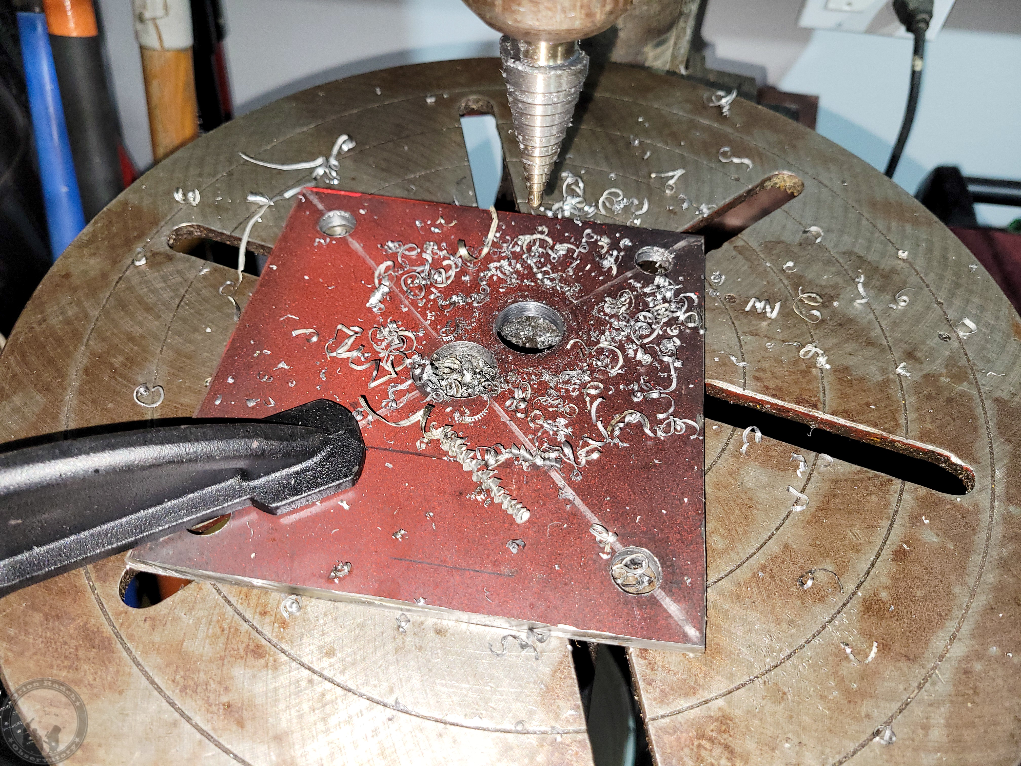
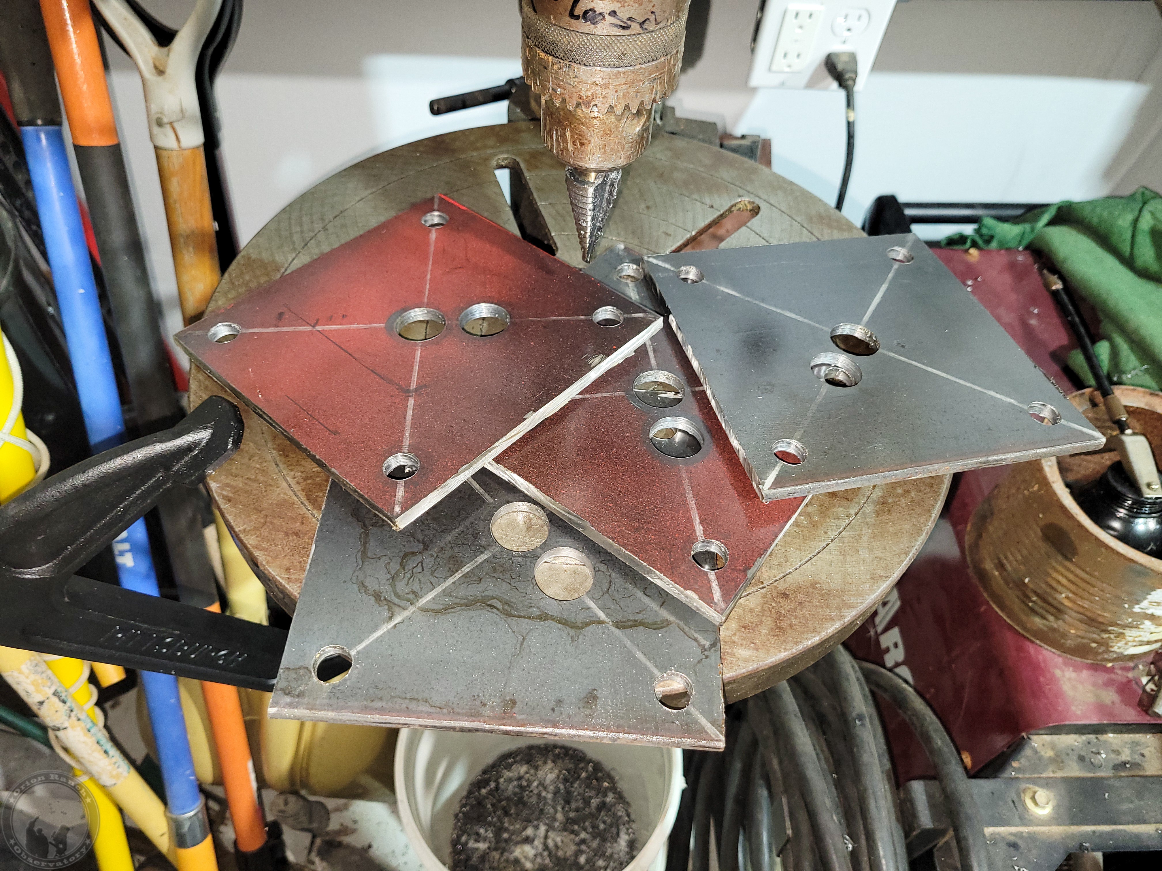
I then proceeded to cut off a 6″ strip from the 2′ x 4′ x 1/4″ plate that I bought that’s on the trailer under the beams so that I can’t actually pull it out completely! I then sliced that into four ~ 6×6″ squares and drilled a large center hole and four corner holes. I was going to do 8×8″ base plates, but those would end up hanging off the round piers on the West side where they weren’t poured in the right place (I’d aligned them off the slab, which turned out to be crooked!) Instead, I plan to rotate the base 45 degrees so that there are triangular tabs on each side giving me more room to install additional anchor bolts after the post is in place. Since I plan to add the corner anchor bolts after everything is in place, the center stud will be the only thing holding the plate and post initially. I’m debating whether or not I’ll actually put the nut on the center stud or not. I don’t expect to ever need to remove the steel, and anyone taking it down would be chopping up steel anyway, so who cares if they have to cut the post bottoms too?!! I just want to be sure I can shift the base a bit in the oversized center hole if needed.
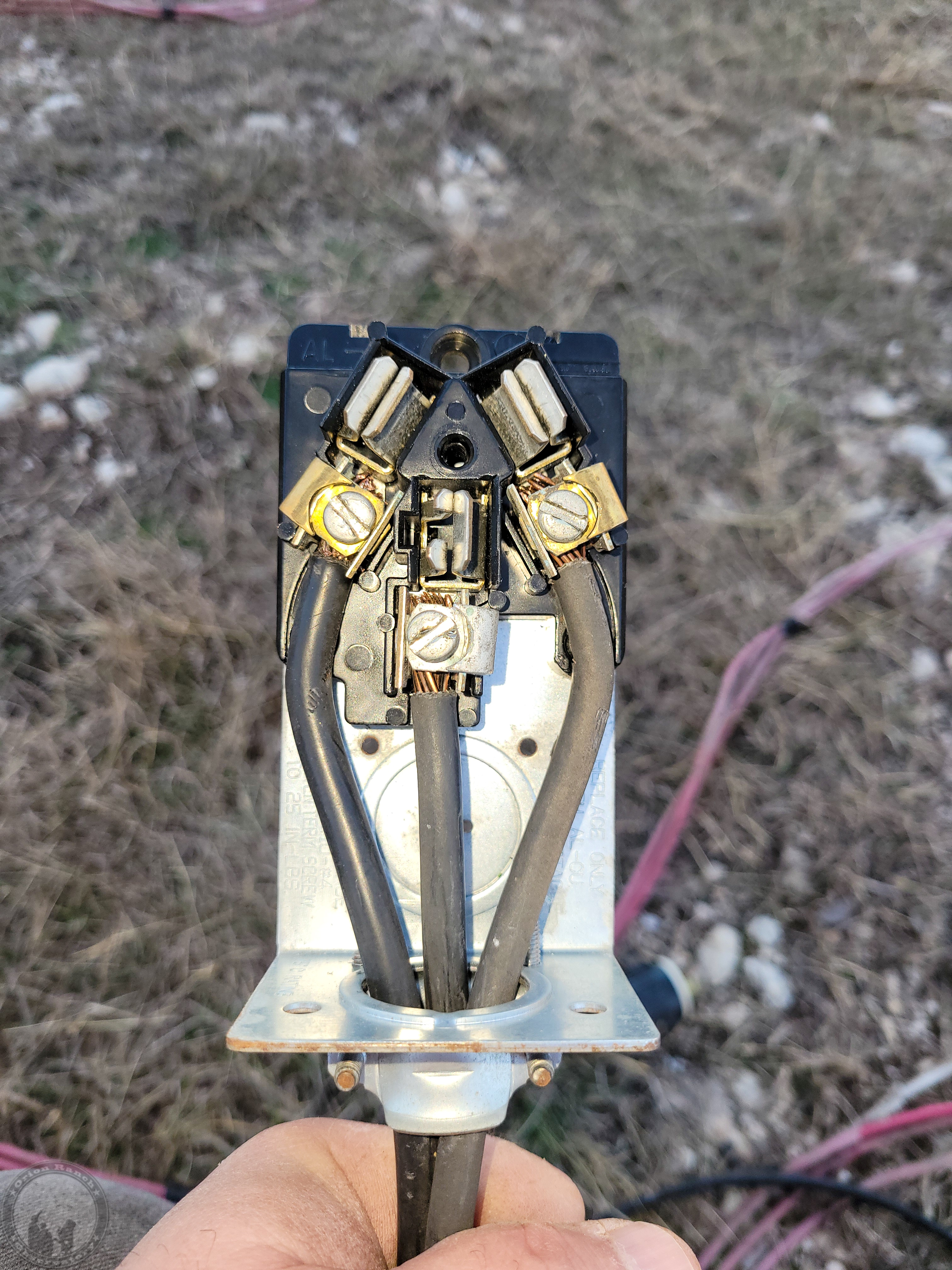
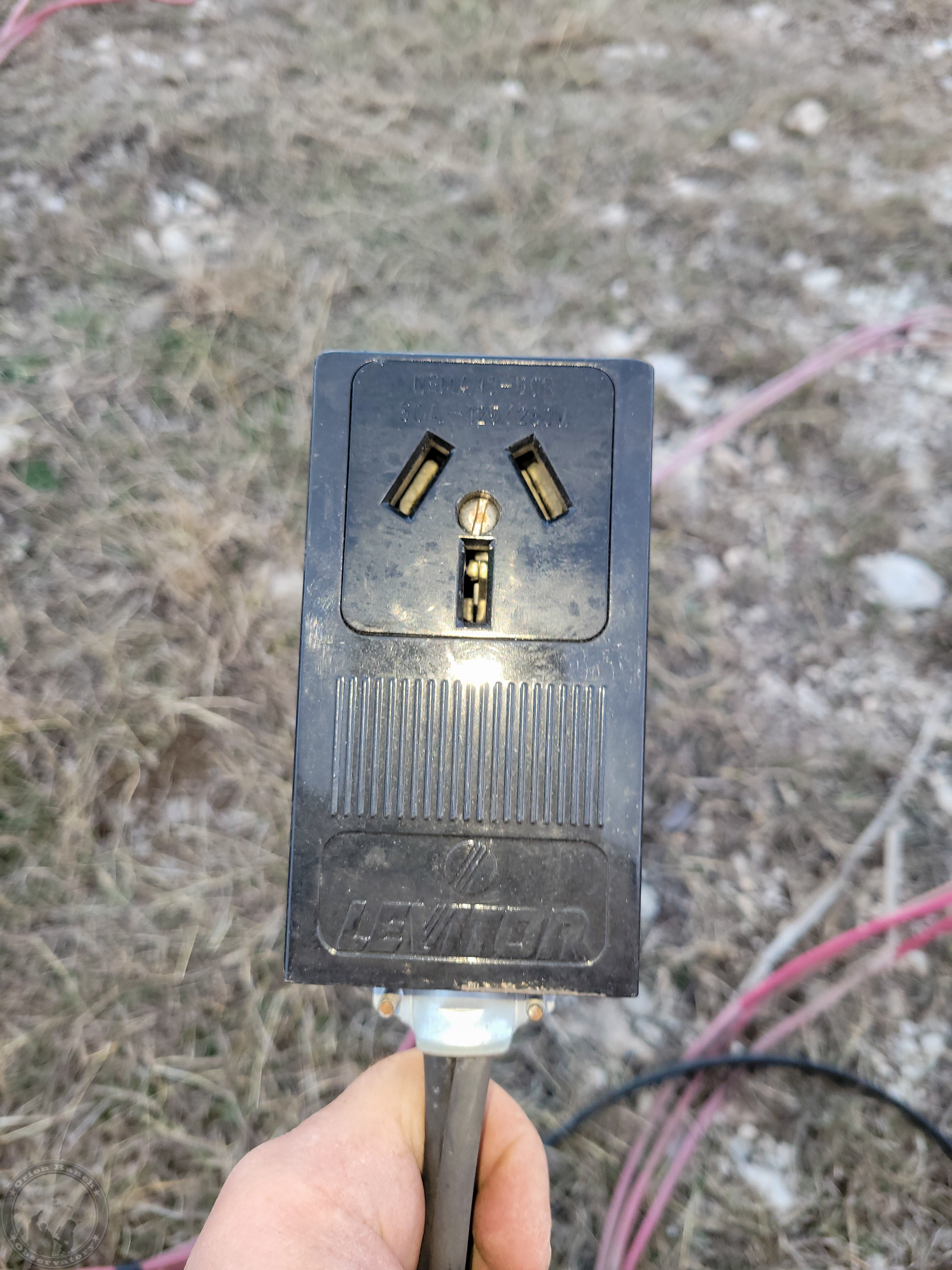
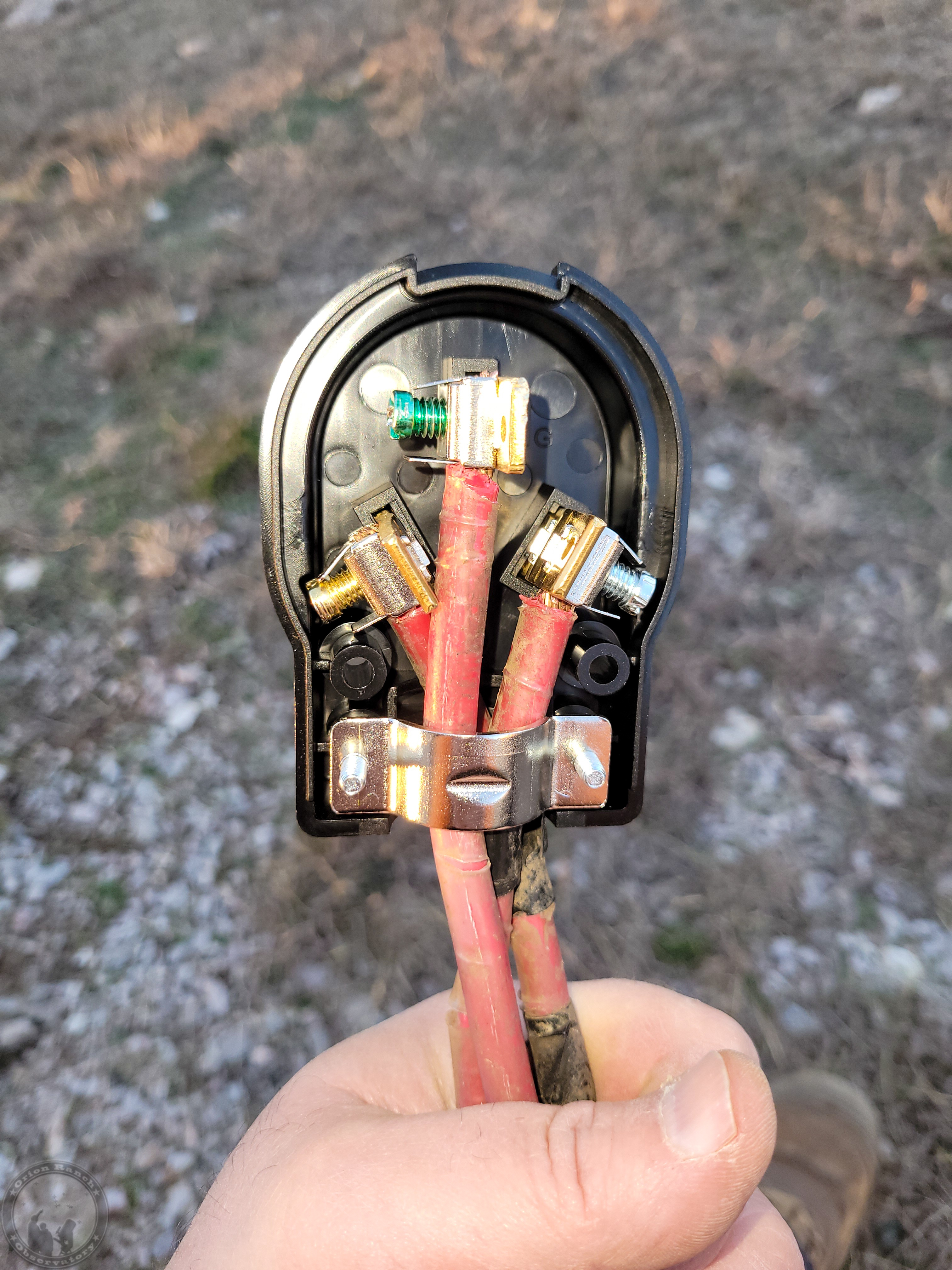
Finally, I put together the 2 AWG welder cable with the new plug that arrived from Amazon. Unfortunately, I realized after the fact that the outlet I’d bought at the local big box store years ago and never used wasn’t actually the correct 50 Amp outlet, but a 30 Amp one (right angle ground and a narrower slot). At this point I’ll just take off the cover and widen the slot, but annoying nonetheless!
I should have the tractor repaired by next weekend and can hopefully get some posts in place!
January 10th, 2026
I received the replacement hose last Tuesday and was able to repair the front end loader on my tractor. It wasn’t exactly as advertised (rated for 4785 PSI instead of the listed 5300) and doesn’t quite fit and bend like the original, but at least I’m operational again. The cows were happy to get another bale of hay!
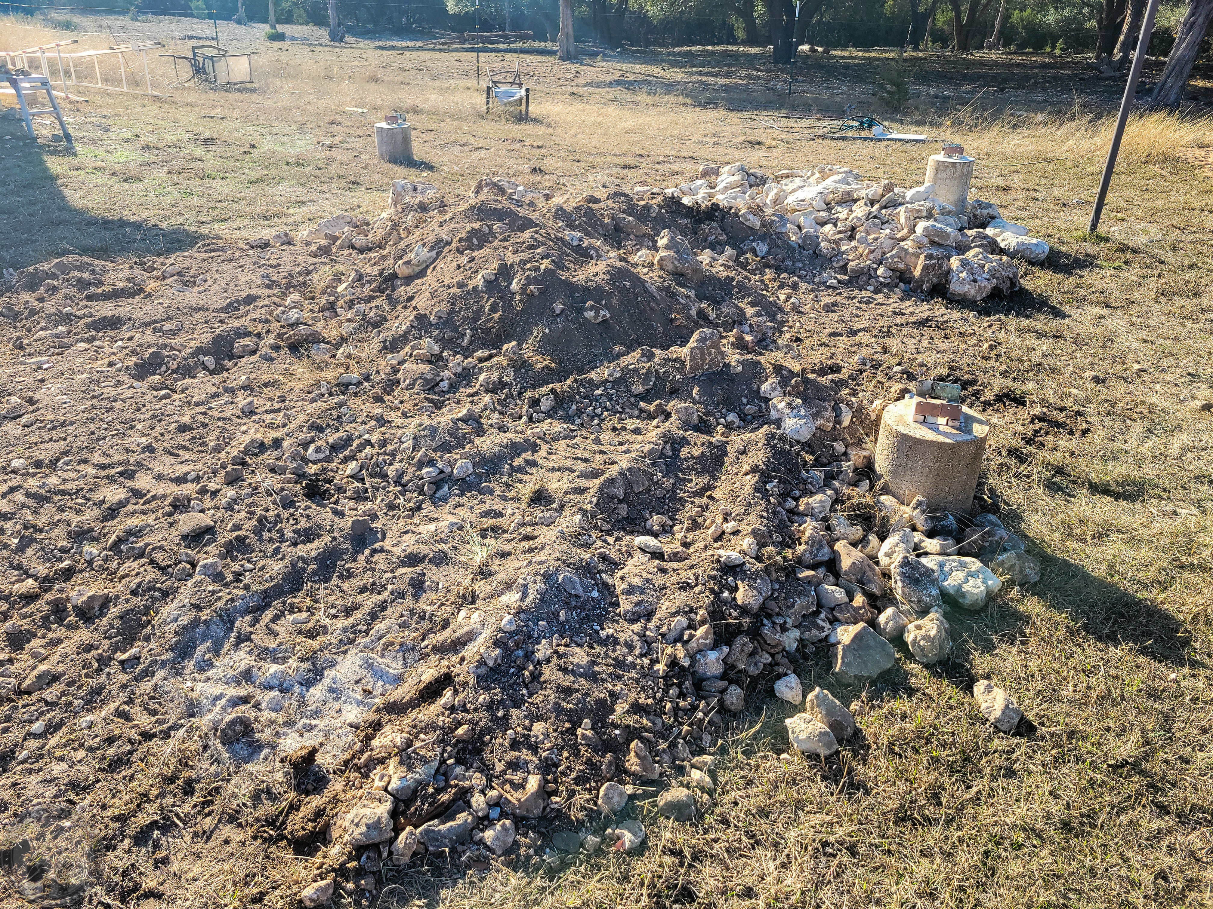
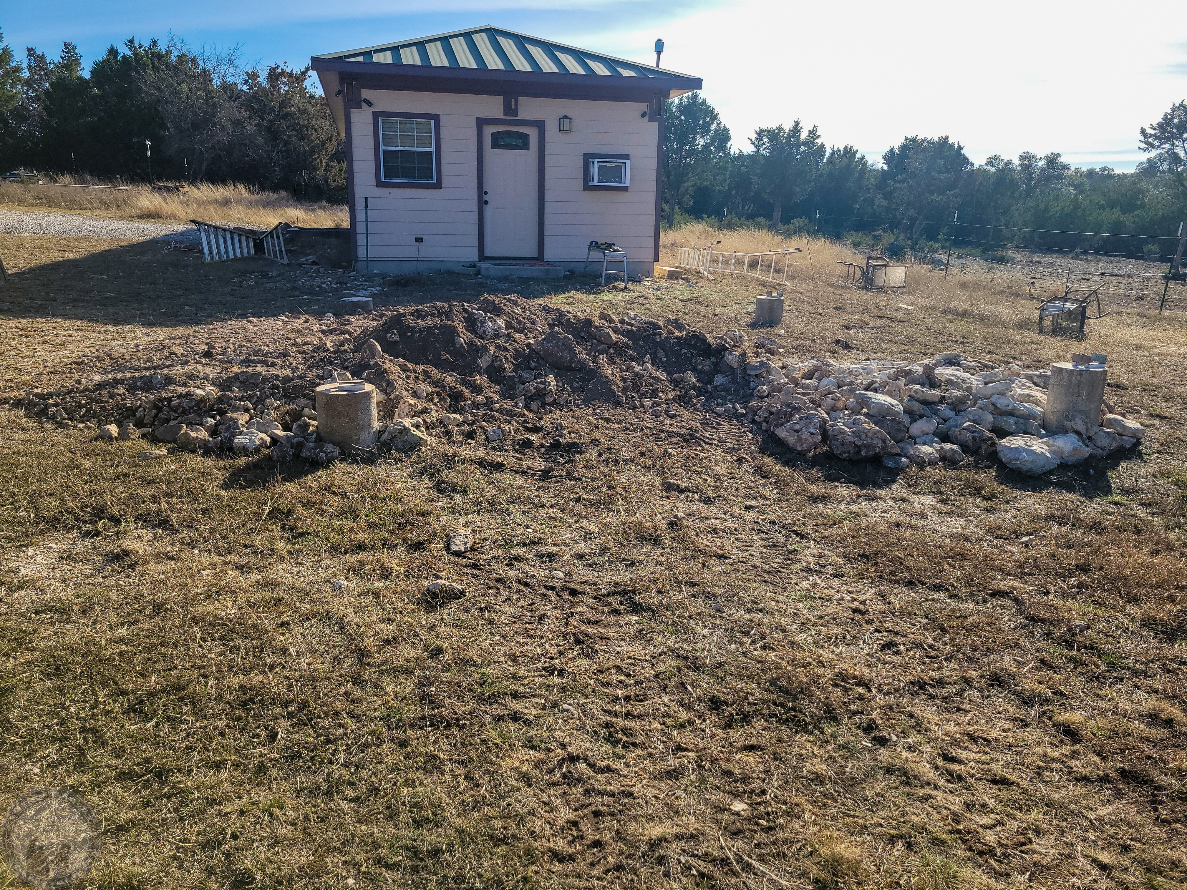
I didn’t get to putting up any steel yesterday, but I did get a nicely leveled pad in place. Still a bit more to do to it, but this will probably do for now.
January 12th, 2026
In answer to one of the questions on Cloudy Nights regarding where I got my steel and what it cost, I checked with several local (Austin metro area) houses and the two that gave me quotes were in the same ballpark. On the other hand, Metal Mart, which is in my back yard, comparatively, was worthless to try to work with! At any rate, with tax, the lot was $4153. For piece part prices (excluding tax) a 24′ 4x4x0.25 for my posts weighs 293 lbs and was $313.44. A 25′ W12x14 H-beam was 350 lbs and $406. A 24′ 2x4x0.120 for my cross braces was $125.52 for 114 lbs. So, on average, figure about $1.05-1.15 per pound here in Central Texas at least. That was with me picking it up.
And just as a reminder, this is already way overkill in terms of strength for replacing the wood that I took down. And just for grins, I calculated what replacing all the wood from Home Depot would cost and it was $770.56 plus tax. I’m sure I could have easily been strong enough at half the cost or even a third, but I’m confident this won’t be going anywhere, assuming I can get it welded right!
The main reason I ended up at the size I did for the beams was to attempt to have something that would be close to the same dimension as the original rail to fit the slots in the observatory cleanly. I really wanted something wider that could have had the flange act as my capture mechanism, but I needed to keep the web directly under the angle iron, so that limited my options. Thus, I have to use a 1×3 tube to add that. I debated just coming up with a hook for the end of the roof only, which would probably have been sufficient, but oh well…

January 17th, 2026
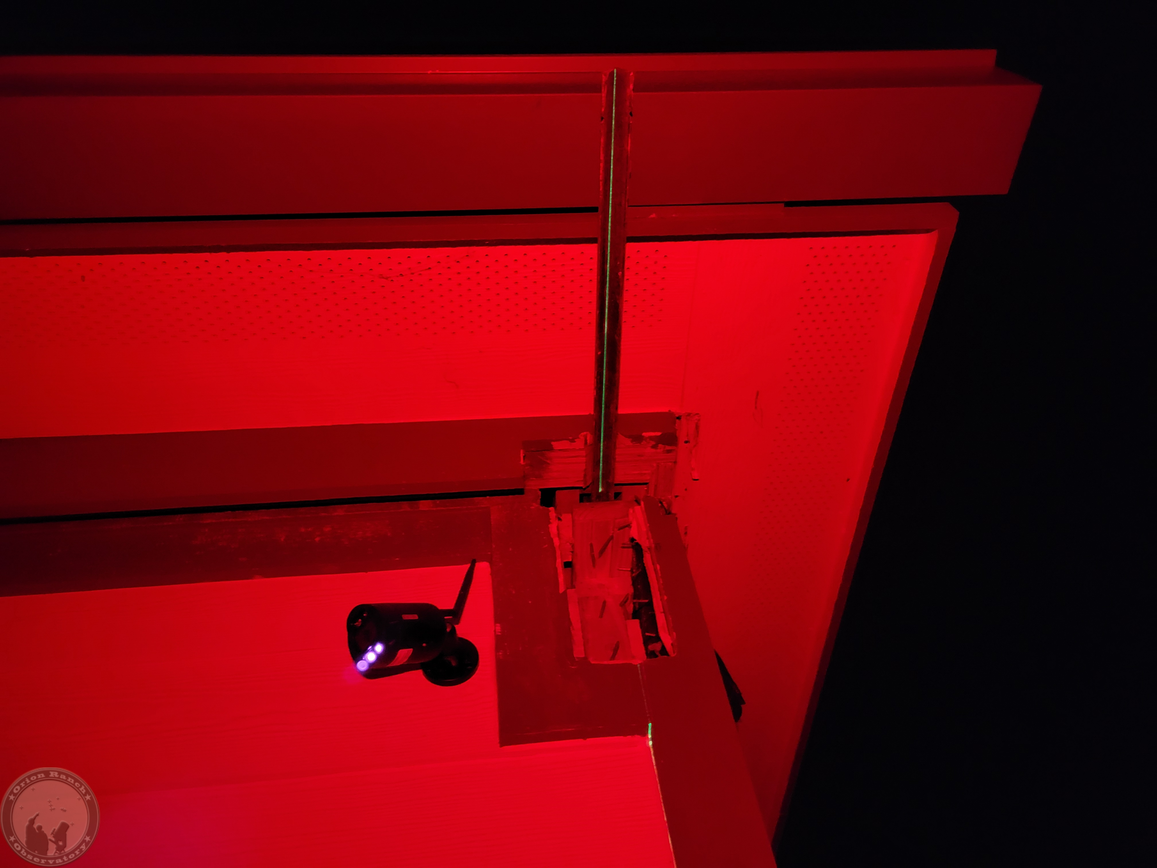
I still didn’t get to welding anything, but spent most of my time stringing guides from the sides of the observatory to check on the alignment.
Translating that inward by the distance marked on the observatory slab using the laser gives me a 189 inch separation. The actual rail separation is 188.5″, so that’s not perfect, but close. I’m going to try the laser level again after dark to see if it’s one side or the other or just split the difference. A quarter inch isn’t going to make much difference one way or another.
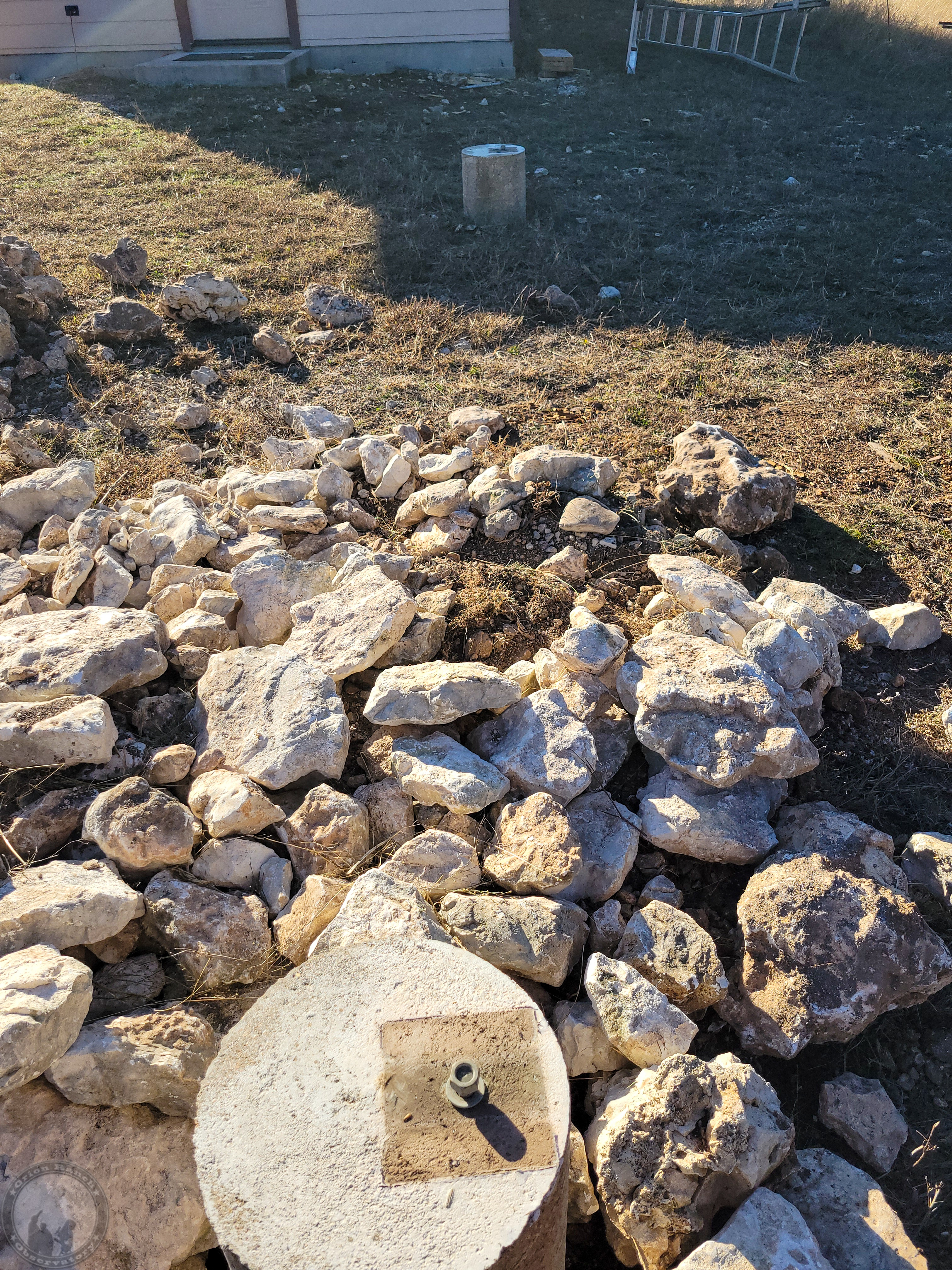
The biggest problem is that the centerline is outside the existing studs, putting it even further to the edge of the western piers, so that one corner is going to hang over the edge.
The east side is looking right on center, where sadly there’s already the original stud cut off!
I’m going to have to either re-drill that center hole on the plates or possibly even just remove the existing stud and just use the corners. I know I should really just knock out the off-center piers and re-pour them (probably should have poured them with a welding plate embedded) but I didn’t want to take the time or effort. I may come back and pour an additional side to the west piers, although I don’t really think I need them structurally.
I went ahead and removed the two end pieces of the capture rail/trim system in order to expose the end of the rail and allow access to the last wheel. That will let me wedge in some support and remove the end of the cap rail under the wheel.

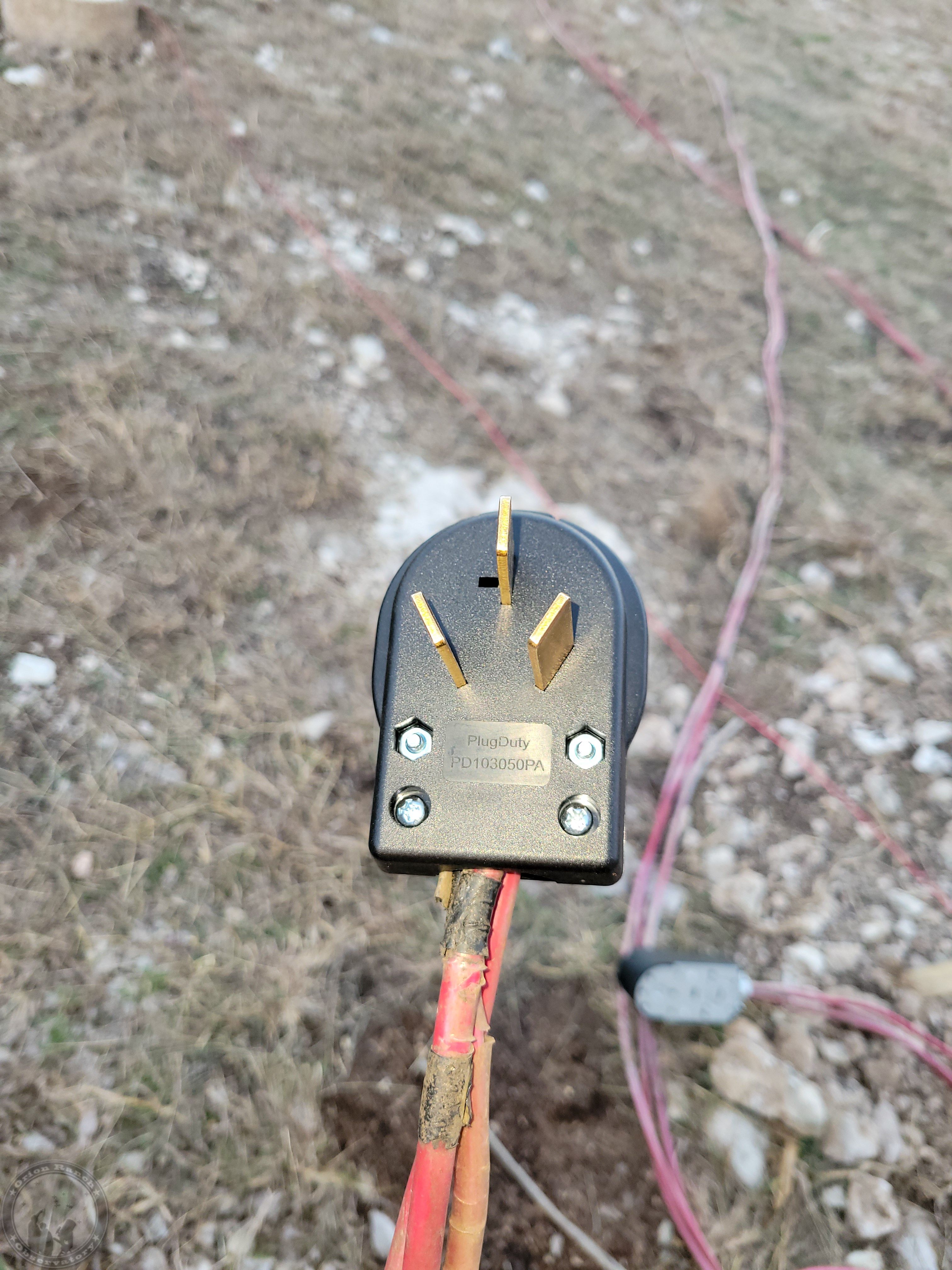
I also took the oscillating saw with a small blade to the ground pin socket on the plug let me open it up to take the 50 Amp ground pin.
January 18th, 2026
Aligning the self leveling laser on the marks from yesterday, they hit the V-groove angle iron rail pretty well, but if you look closely, there’s a bit of front-to-back variation on where it’s hitting. The other side was about the same.
Adjusting the west side by about half an inch to shoot for the 88.5″ separation still looks about the same on the angle iron.
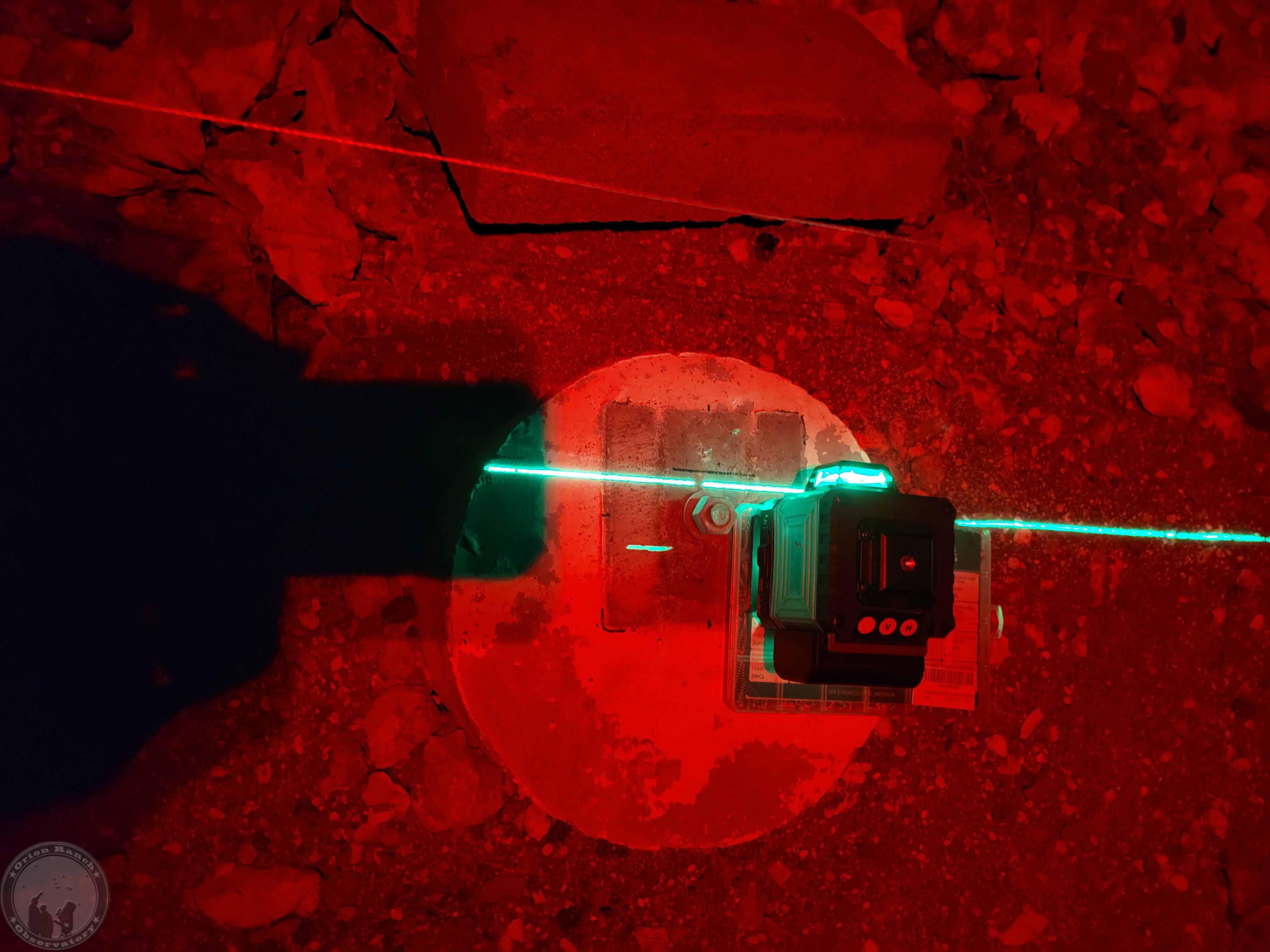
However, attempting to align the laser down the center of the V-groove angle iron, it hits the bolts perfectly! Same for the other side. Not sure the spacing is quite wide enough, but I’d be much happier to be centered on those bolts! I still think I’ll have to widen out to 88.5″, but we’ll see how that goes.
January 19th, 2026
Going back and reminding myself of the original rail design, the angles are centered on the 2×4 walls, so (16′ = 192″) – 3.5″ = 188.5″, while the old posts for the rails were 6×6’s, so 192″ – 5.5″ = 186.5″. Thus, to center the new posts, under the angle, I need to move them out 1″ each side. The old posts weren’t centered under the rail, they were aligned to the outside.
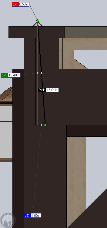
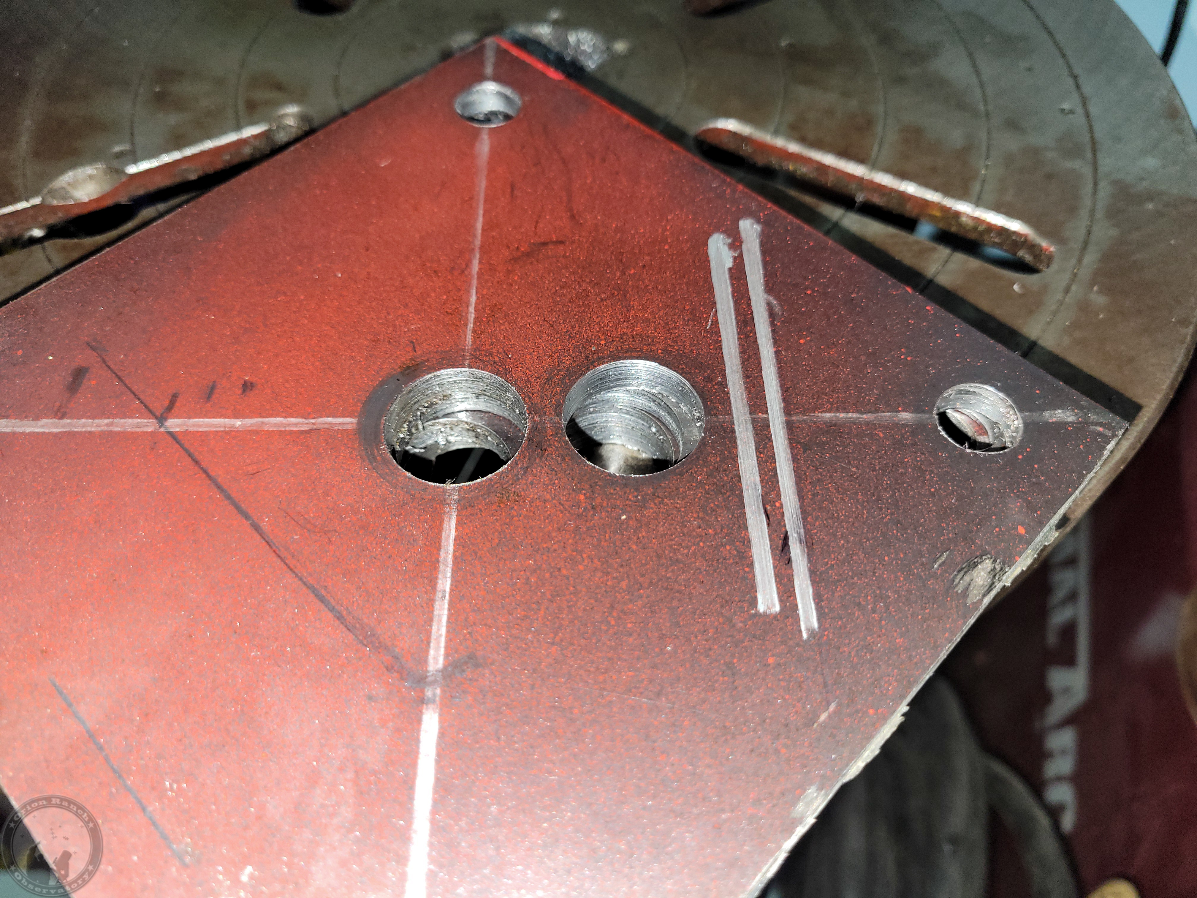
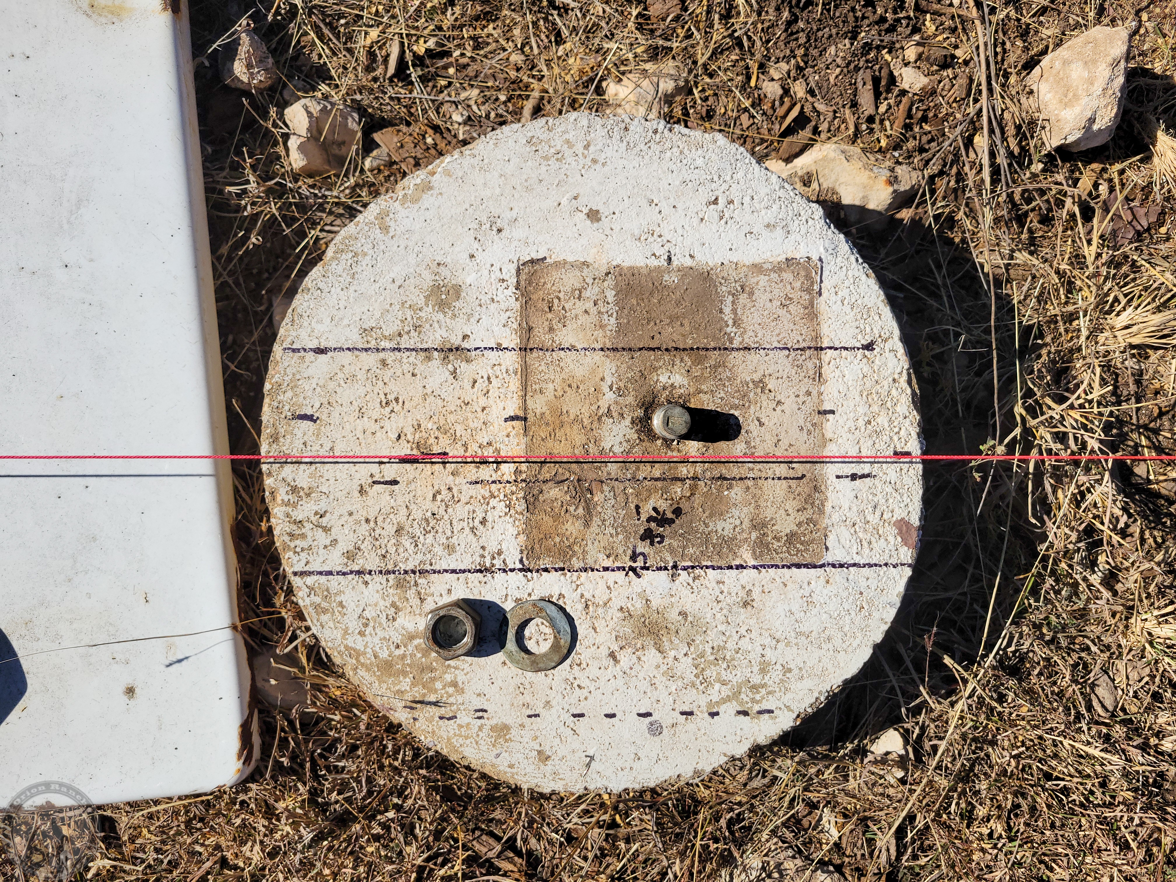
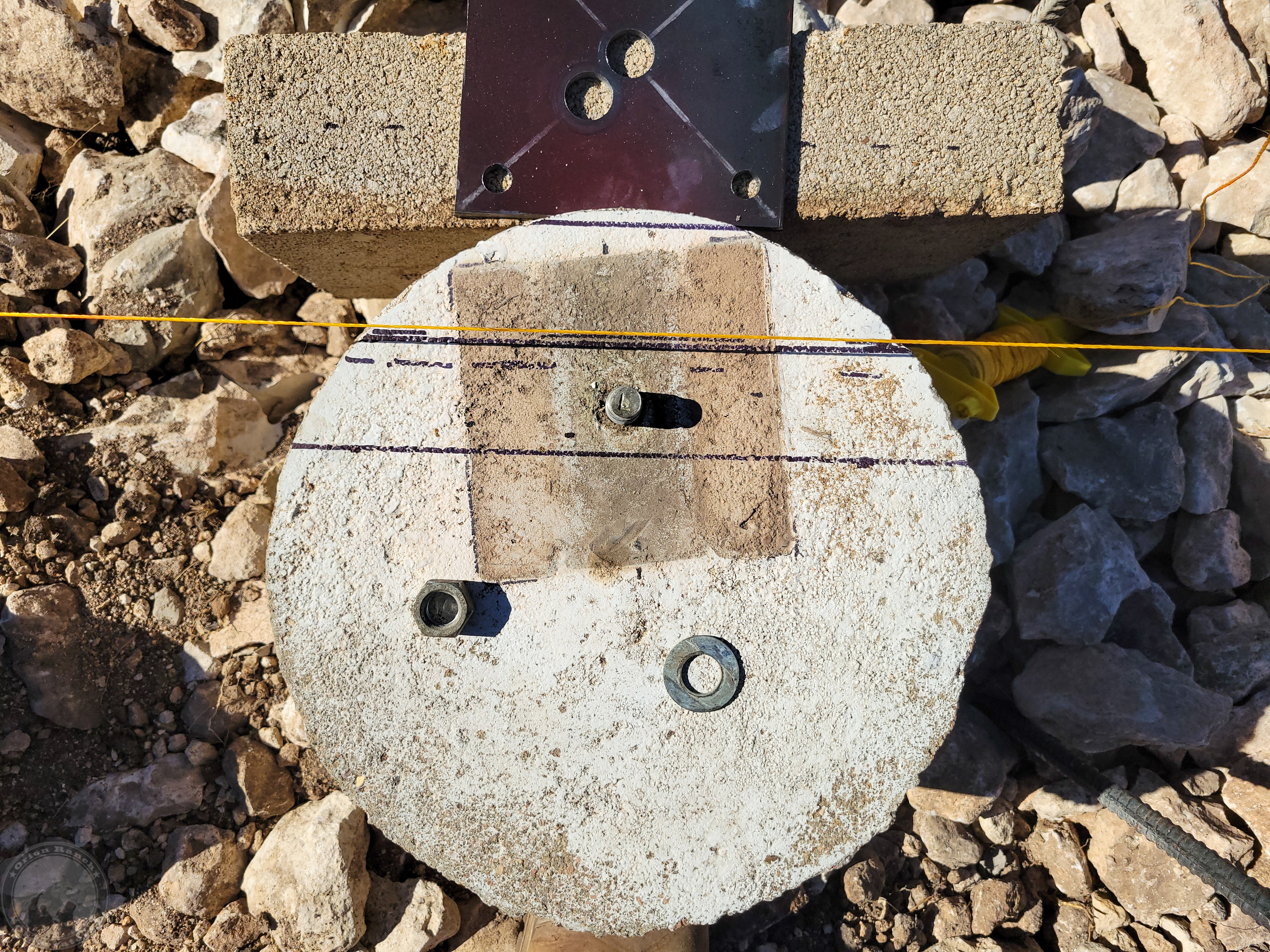
The 6×6 post was 1″ offset from the center of the rail, so I need to offset the center stud hole. This was the 1/2″ pilot hole that then gets expanded to give some play to the location.
I then have to widen the holes out to give some play.
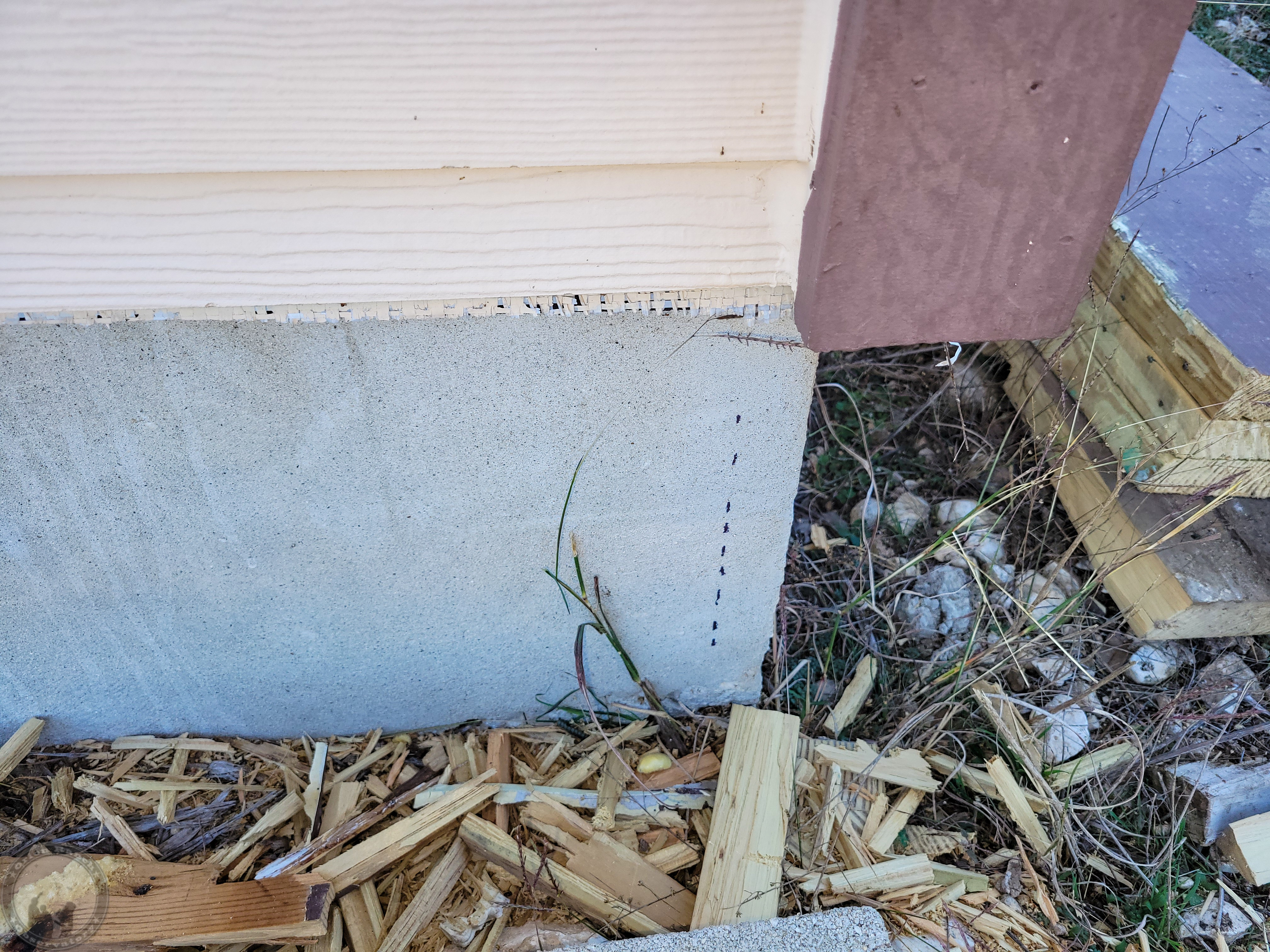
To get an idea of how close the post will end up to the new hole, I drew these lines 2″ from center and 1/4″ inside that.
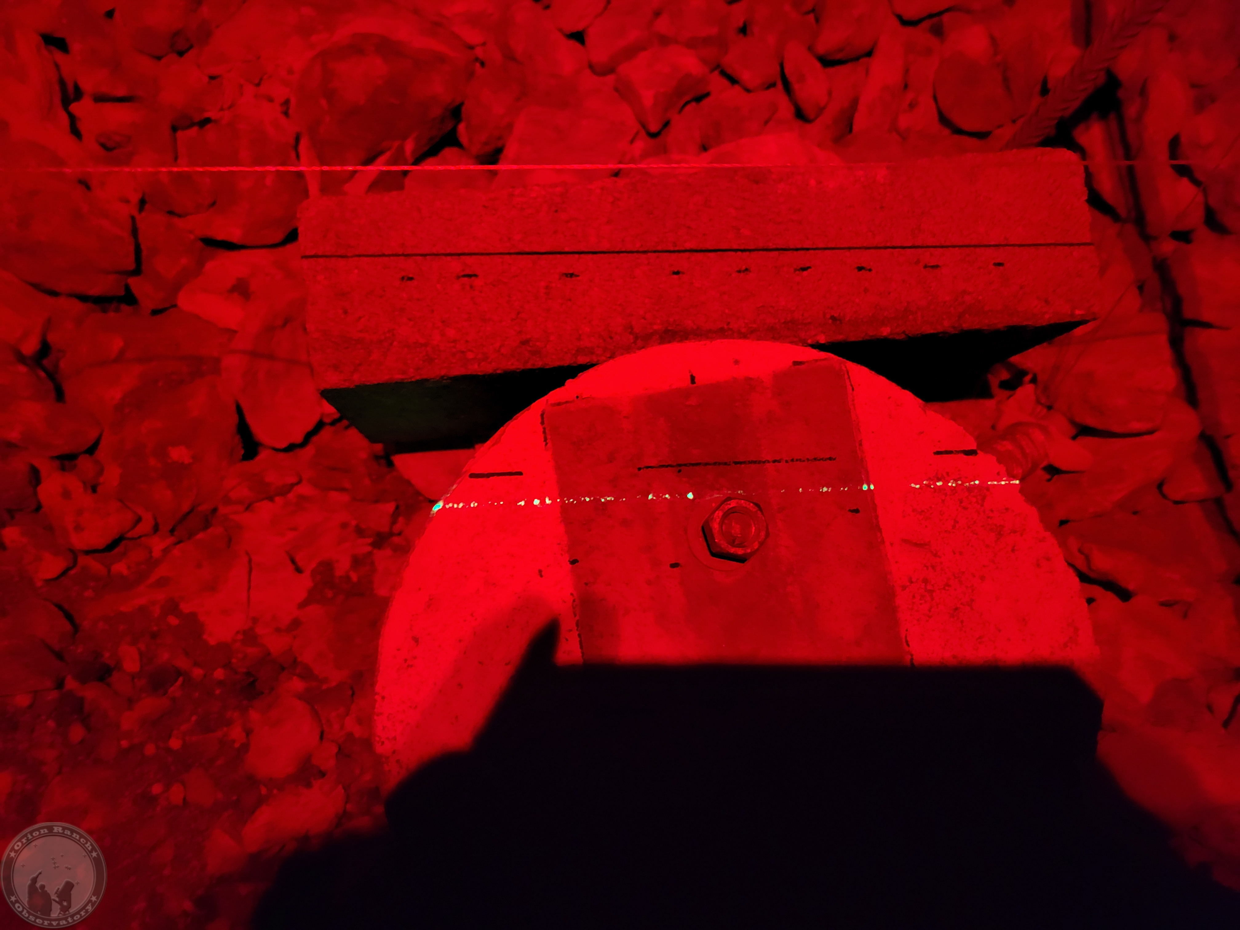
I moved the strings over to map out the centerline for each beam and adjust the spacing as needed. I then drew the 4″ wide lines for the post location. These pictures were taken around the time or just after the Sun was at Zenith, so the shadow of the string was right on my line!
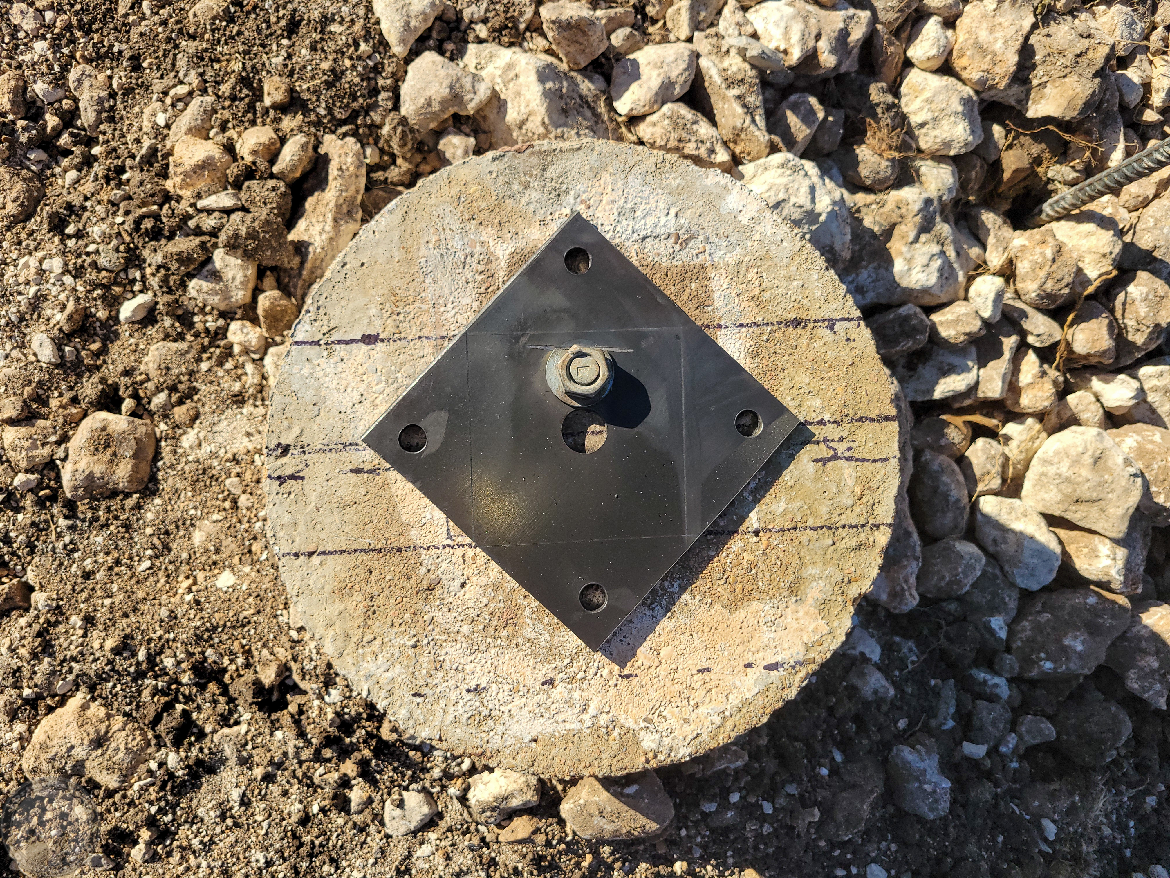
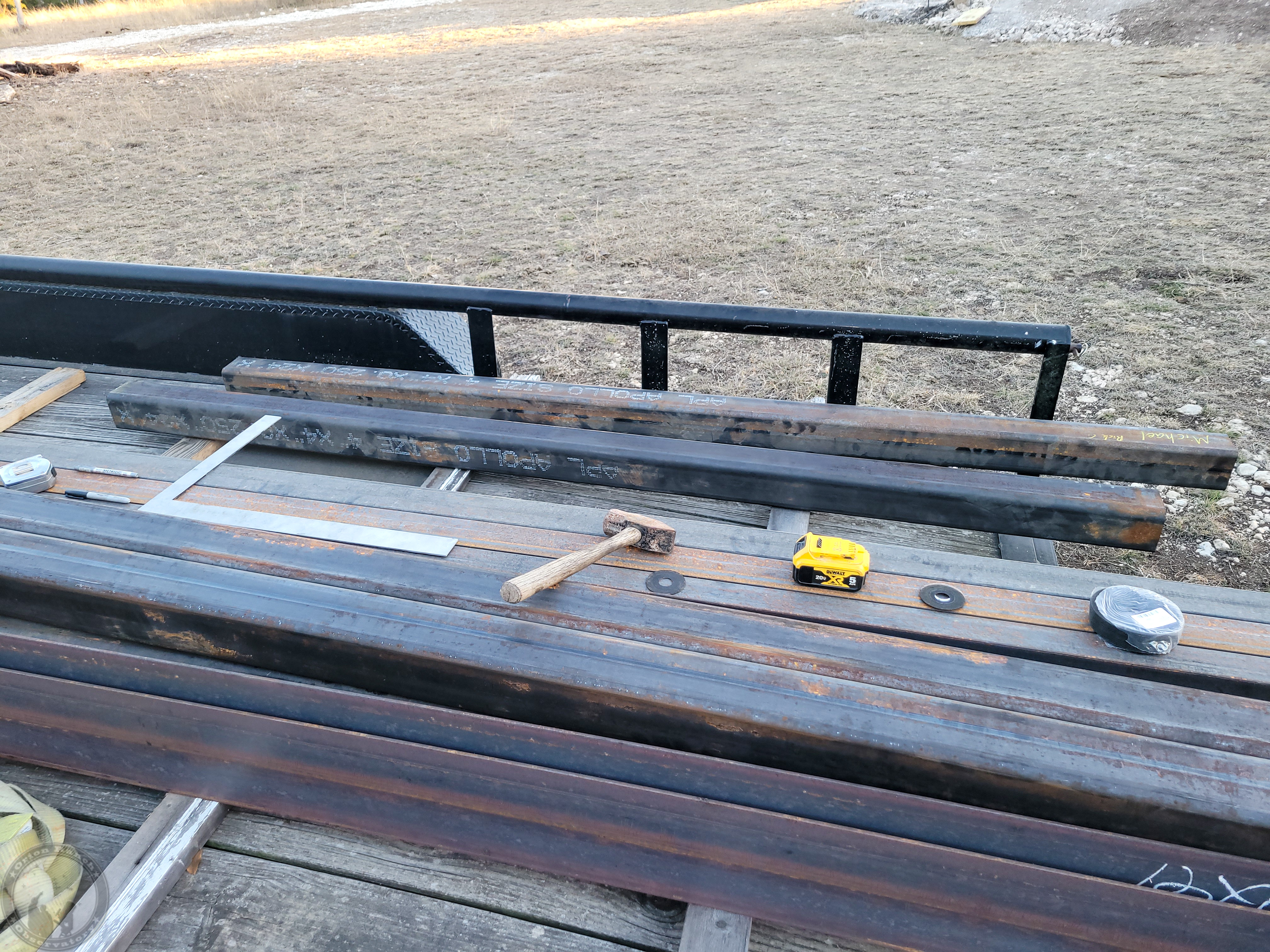
I then installed the plates on center and polished them with a wire brush wheel to remove all paint, etc. I had to cut out between the holes on one in order to get it to the right spot. I then scored a 4×4 guide into each plate.
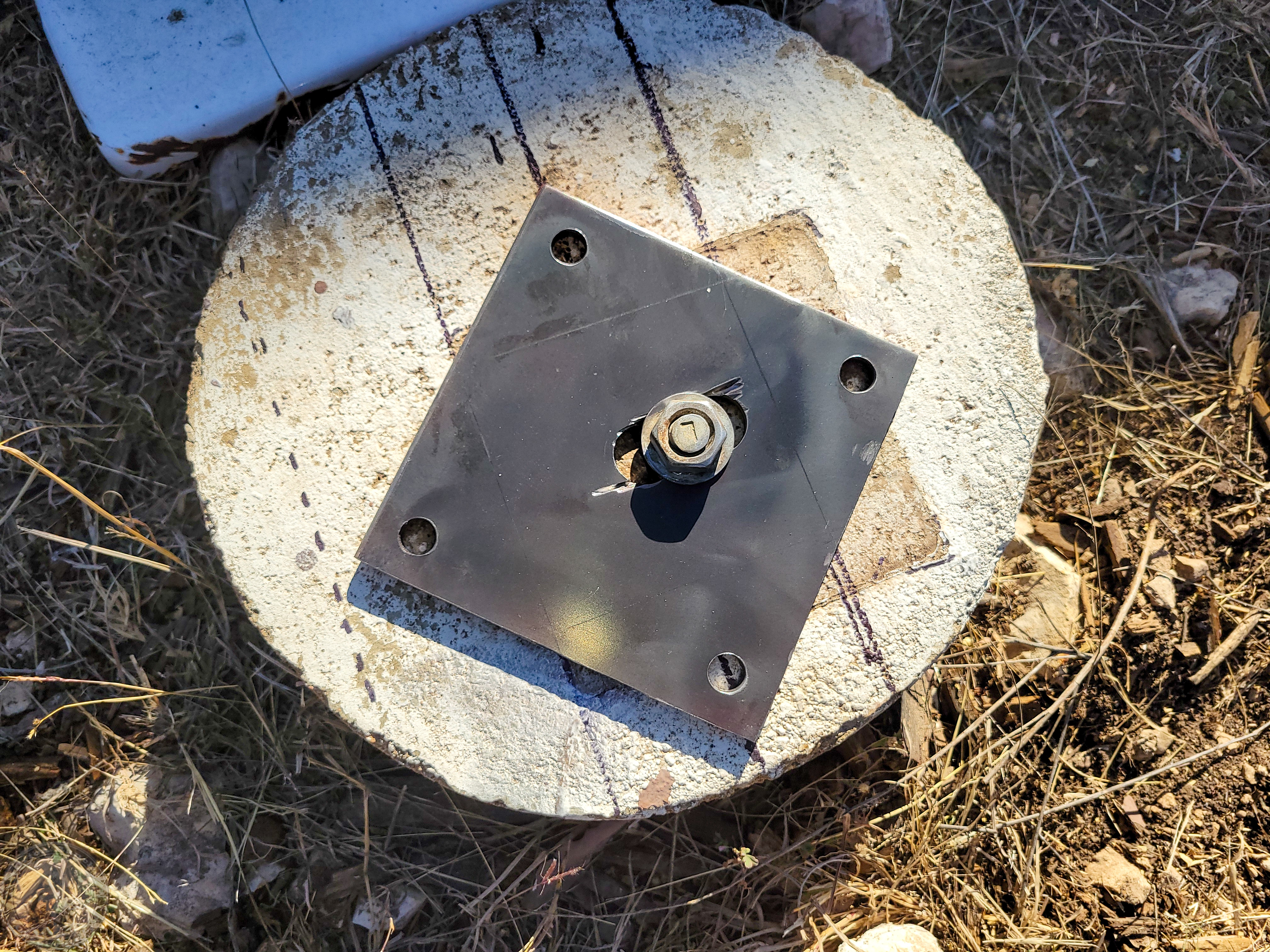
I also cut back a couple of the washers to be sure they didn’t interfere with the post.
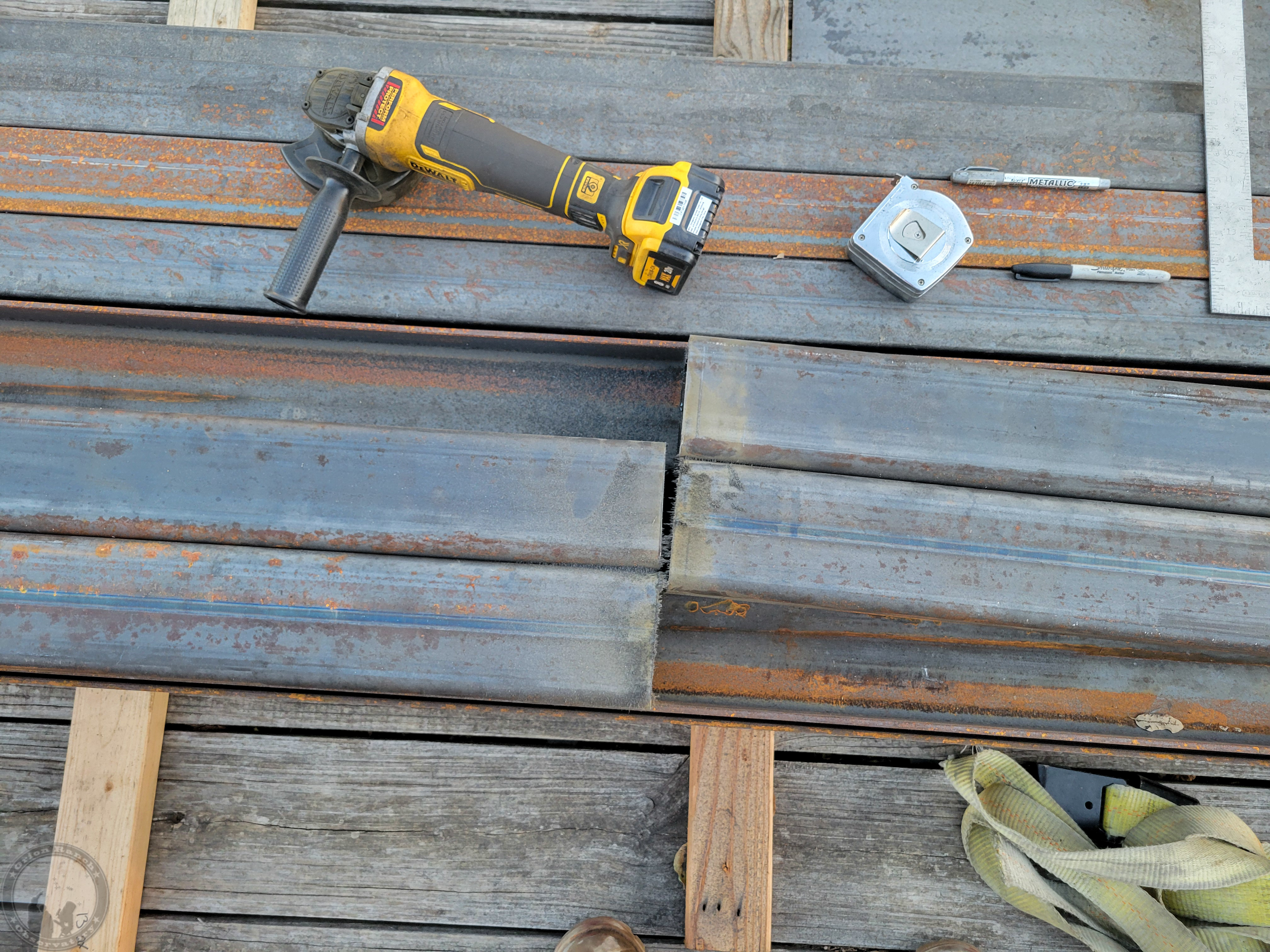
I then cut the 24′ 4×4’s into four posts. Unfortunately the length needed to be a bit more than 8′, so I couldn’t get three posts out of one piece as I’d originally planned. Ah well. I cut the posts at 8′ 2″ that should have them a bit long. Once they’re installed, I’ll mark them with the laser level at the required cut height so that they’re all at the same level. That’s still a bit problematic as there is some variation in the size of the beams.
The last cut!
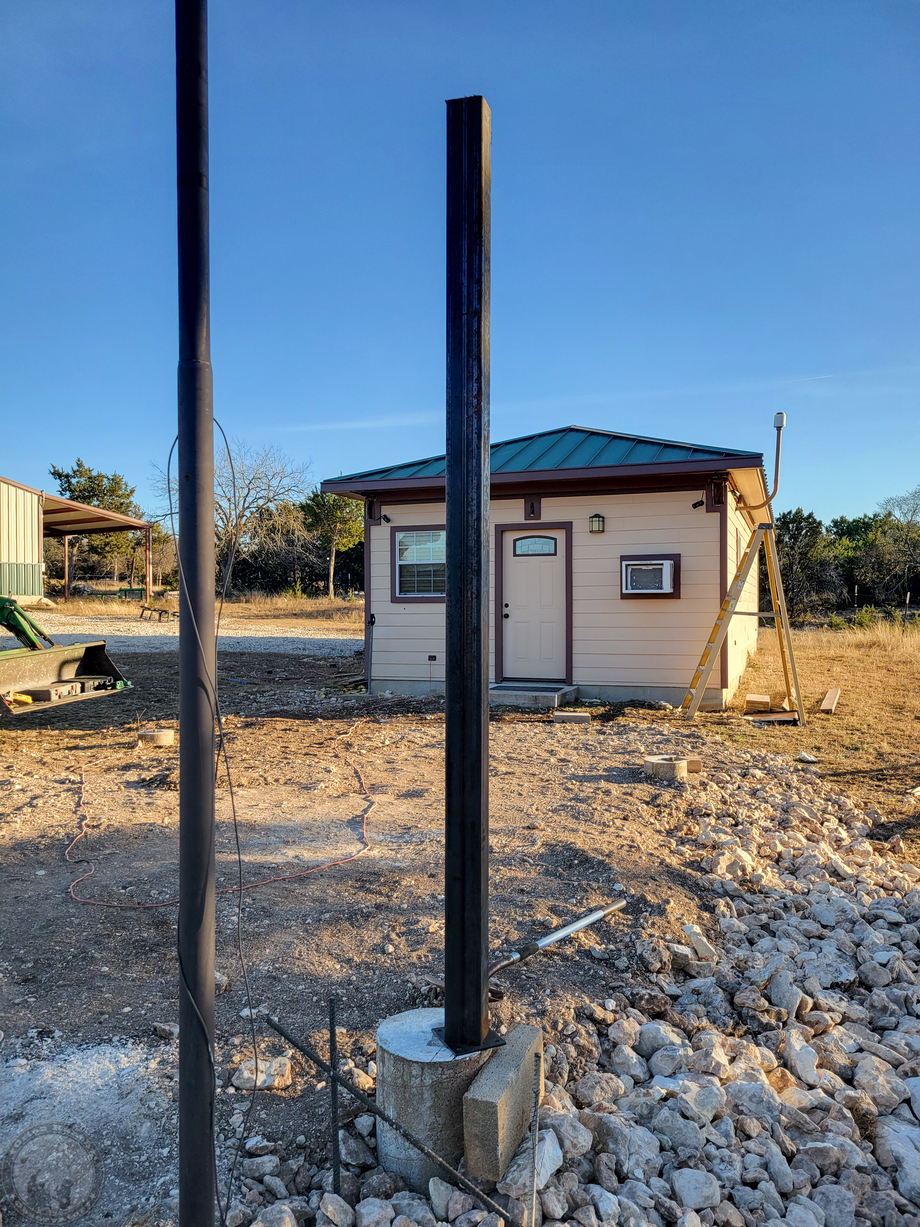
It was getting too late to drag out the welder, but I had to put one post in place temporarily just to get a look!
January 25th, 2026
After 2.6″ of rain followed by ~1/8″ accumulation of freezing rain, we had about an inch or so of graupel snow (between snow and sleet) overnight. Some nice 18″ drifts where it all came off the valleys of our roof. Thus, the lack of progress on the construction this weekend!