Ok, after lots of research and experimentation, I’ve completed my Arduino Nano based GPS for replacing the NexStar GPS modules. I’m going to give a detailed walk through of everything here so that it’s well documented, although it may take a few posts due to the picture limits per post. I started from Barry’s repository on GitHub because he was doing the same mount and I didn’t need the display that others have added. However, what I didn’t realize until I was part way through everything that the firmware there was incomplete and never actually worked. Thus I had to merge some of Miro’s (ForestTree) fork back into my code to complete everything. There are two main changes I made. The first was to fix the serial interface so that it works as Celestron intends it to without any additional hardware (no diodes, etc.). It also uses the busy control line like it’s supposed to. The second was to add support for the GNSS NMEA sentences so that it responds to the $GNxxx sentences that the BN-220 generates when GLONASS satellites are visible, as well as the $GPxxx sentences from straight GPS. I’ve created a fork from Miro’s version at https://github.com/L…ulf/nexstar_gps. The way I uploaded it did a full replace on the .ino and isn’t giving a proper difference view, but I didn’t want to fool with figuring out how to fix it. If someone wants to give me an easy way, I’ll see about doing so, but there are plenty of other difference viewers you can use.
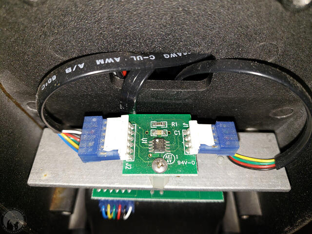
Barry’s wiring description wasn’t very clear on the wiring to the telescope, so I had to reverse engineer the NXW434 PIC microcontroller board that the Arduino is replacing.
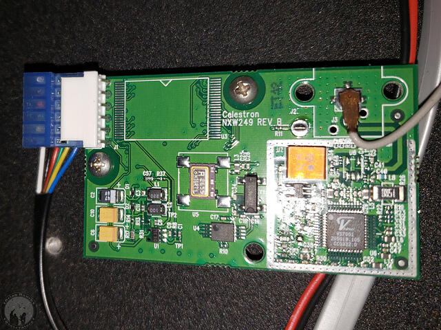
This connects to the NXW249 GPS bpard:
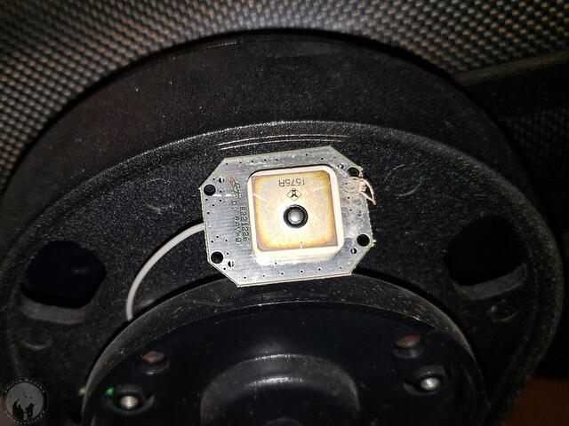
which coupled with the active GPS antenna makes up the parts being replaced by the BN-220.
I created a schematic for the NXW434 and posted it in my repository.
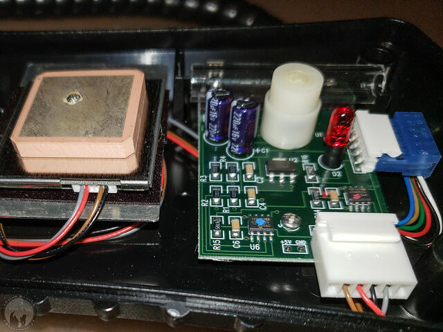
For reference, I also opened up my CN16 and found the exact same circuit combinations. You can see the blue AUX serial connector on the right and the white GPS connector in front. The newer CPC style GPS module is under the antenna similar to the BN-220. Two Microchip 12F629 PICs identical to that on the NXW434 provide the serial interface. The PIC with the red dot is the equivalent of the NSW434, while the one with the blue dot runs the compass and level (long clear tube with a metal ball in it) at the back. Those latter components are elsewhere in the NexStar GPS.
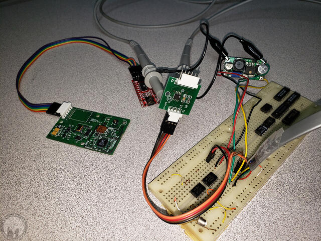
Rather than removing the NexStar GPS from the observatory, I rigged up a voltage regulator so I could plug the NXW434 into my NexStar 8SE mount. (Ignore all the other chips stored on the breadboard. They’re just stored there from old projects!) This allowed me to hook up my oscilloscope so I could monitor the communication and confirm what each pin was actually doing.
So what I had already suspected, then determined with the oscilloscope and finally confirmed looking at the CN16 wiring, is that the four wire interface on the NXW434 is 5V power, ground, the drop/busy line, and a combined TX/RX line. It’s NOT separate TX and RX lines as you might think from Barry’s repository. That’s why Miro’s AVX design works with a single wire. It turns out the hand controller still reads the GPS fine without the busy line being pulled low. It’s just that anything else (e.g. a serial or Wi-Fi interface) could potentially attempt to access the interface at the same time and cause a collision since the busy line isn’t low.
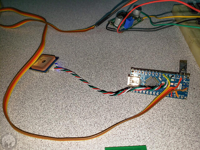
Here’s my Arduino GPS on the test jig. The BN-220 GNSS module on the left is connected to the Arduino Nano on the right. The jumper temporarily connects serial TX and RX pins, while allowing me to disconnect and reconnect the USB serial port for programming.
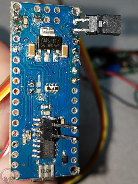
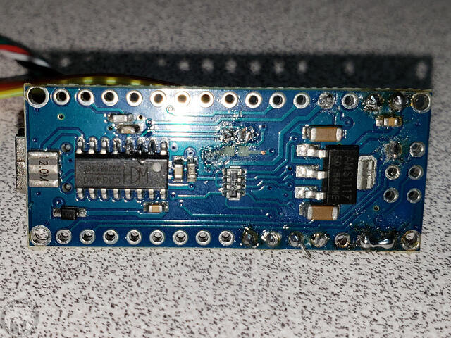
A look at the back side shows more modifications. The resistors in the middle had to be removed because they connect the CH430 (or FT232) to the serial port on the Atmel ATmega processor. (Funny that Atmel was bought by Microchip who makes the PIC processors!) The resistors are relatively low values, but enough so that if you hook up a normal serial TTL connection to the Atmega you can still drive the lines high or low against the signal from the USB to serial adapter. However, if you were to leave them on and connect to the common buss on the NexStars, they’d still drive the line and cause Error 16 and 17 when the hand controller starts up and tries to talk to the motor controller. However, I still needed jumpers for debugging, and started with them on the surface mount pads, but they pulled off quickly. Now they’re directly on the pins. Of course this same arrangement could have been used with an external USB adapter, or you could use an Ardunio mini with separate adapter like Miro’s setup.
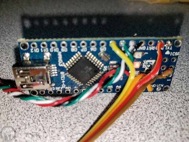
Here’s a closeup of the wiring after removing all the jumpers (after programming it first!). As you can see, no additional circuitry is required. The schematic for this setup can be found here. Note that I might have rearranged the location of the drop line vs. the GPS software serial port had I not already soldered up the GPS connection to match that of the previous designs.
On the back side you can see the solder bridge between TX and RX after removing the jumpers.
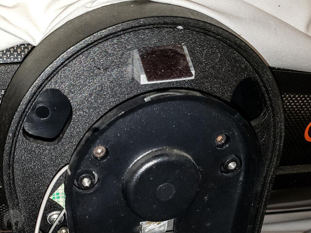
I’ll add picture of the installation later, but the BN-220 module with attach directly on the double-stick tape that I pulled the active GPS antenna off of.
The Arduino and wire will then route down to the connector at the bottom of the fork arm.
Note that the exact same firmware and circuit board setup can be used to connect to the AUX port on any Celestron mount. Simply feed the +12V line into the Vin pin of the Arduino Nano. You can find the schematic in my repository here. At this point I’m debating turning my NexStar 8SE into the (presumably) first NexStar GPS 8SE, adding this mod internally. That way I don’t have to fool with the CN16 anymore.
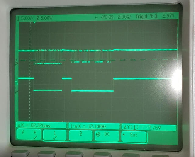
I’ll be posting a video of the testing when I have the chance, but here’s a screen shot from the oscilloscope. This is showing a transaction between the hand controller and motor control board. The top trace is the serial communication. The bottom is the drop line, presumably named that because you drop it low to indicate busy.
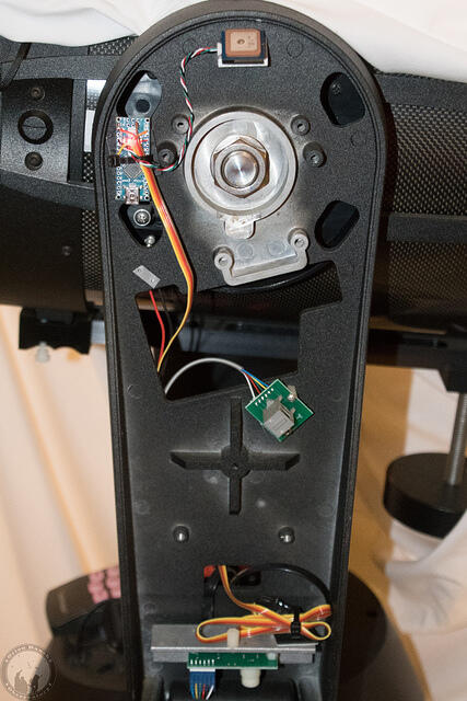
After installing the upgrade in my NexStar GPS, this is what it looks like.
I attached the GPS module directly to the previous sticky tape and used a tie-wrap pad to attach the Arduino nearby. I had made more than enough cable to reach the connector, but went ahead and left it long, which meant bundling at the end with another tie wrap sticky pad. I went ahead and routed behind the arm like the RF cable had run to the old GPS module.
The modification works fine, although I can actually see the blue GPS LED shining through cracks in the case, so I might get in there and cover it up someday.
I also decided to order another BN-220 and quickly built an internal GPS modification for my 8SE. Works great! I would hazard a guess that this is the world’s first NexStar GPS 8SE!
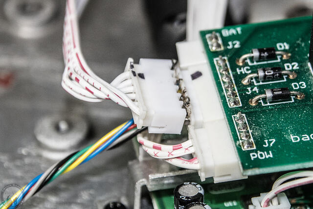
I created a jumper to tap in to the hand control connector on the serial board so that I didn’t have to modify any of the internal parts.
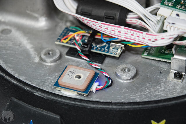
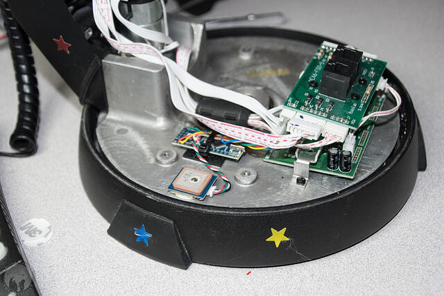
The body of the arm is all metal, so I had to install the GPS in the base, but it works fine there.
At any rate, hopefully all this will help others who want to make this mod.










2 Responses to Arduino GPS Replacement for NexStar GPS